
HP Virtual Connect for c-Class BladeSystem Version 3.30 User Guide

Virtual Connect networks 97
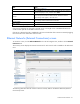
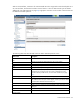
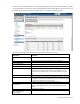
Defining a shared uplink set
To define a shared uplink set:
1. Enter the shared uplink set name. The uplink set name can be up to 64 characters in length (no spaces).
2. Use the cascading menu to select a port, and then click Add to add one or more external ports. Only
available ports are listed, and they display the current port link status. Select two or more ports to ensure
a high availability connection.
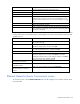
3. Select the speed and duplex (where applicable) of the uplink ports. Click the pull-down box under
Speed/Duplex, and then select a setting. Half-duplex operation is not supported by the VC-Enet
module.
IMPORTANT: Be sure that the uplink interface port speed matches the speed set on the
corresponding network switch port. If using autonegotiation, both ports must be configured to use
autonegotiation or they might not link.
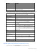
4. Select the Connection Mode:
o Auto (recommended)—This mode enables the uplinks to attempt to form aggregation groups using
IEEE 802.3ad link aggregation control protocol, and to select the highest performing uplink as the
active path to external networks.
Aggregation groups require multiple ports from a single VC-Enet module to be connected to a single
external switch that supports automatic formation of LACP aggregation groups, or multiple external
switches that utilize distributed link aggregation. HP has guidelines available for users who wish to
connect to external switches that support distributed link aggregation capabilities.
Multiple aggregation groups may be formed from the ports selected for the network. The highest
performing aggregation group is selected as active, with other aggregation groups and individual
links used as standby connections.
o Failover—If this mode is selected, set the port to Primary or Secondary. Only a single link is used as
the active link to the external networks with other ports used as standby connections.
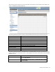
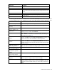
5. Create the Associated Networks that will use this shared uplink:
a. Click Add above the table.
-or-
Right-click the header row in the Associated Networks table to display a menu, and then select Add.
b. To add a single associated network:
i. Select the a single Associated Network radio button.
ii. Enter the name of the network.
iii. Enter the number for the VLAN ID (1 to 4094) for that network as defined by the network
administrator and as configured on the external Ethernet switch.
iv. Select whether to enable (checked) or disable (unchecked) native VLAN. Only one network per
shared uplink set can be selected as the native VLAN. See "Shared uplink sets and VLAN
tagging (on page 70)."
v. Skip to step d.
c. To add multiple associated networks:
i. Select the multiple Associated Networks radio button. Creating multiple associated networks in
bulk allows for a shorter set up time. All networks created in bulk share the same settings. These
networks can be edited individually after they are created.