
HP Virtual Connect for c-Class BladeSystem Version 4.01 User Guide
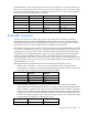
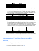

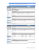
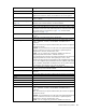
Table Of Contents
- HP Virtual Connect for c-Class BladeSystem Version 4.01 User Guide
- Abstract
- Notice
- Contents
- Introduction
- HP Virtual Connect Manager
- Virtual Connect domains
- Understanding Virtual Connect domains
- Managing domains
- Managing SNMP
- Viewing the system log
- Managing SSL configuration
- HP BladeSystem c-Class enclosures
- Virtual Connect users and roles
- Understanding VC administrative roles
- Managing users
- Local Users screen
- Configuring LDAP, RADIUS, and TACACS+
- Minimum requirements
- LDAP Server Settings (LDAP Server) screen
- LDAP Server Settings (LDAP Groups) screen
- LDAP Server Settings (LDAP Certificate) screen
- RADIUS Settings (RADIUS Server) screen
- RADIUS Settings (RADIUS Groups) screen
- TACACS+ Settings screen
- Role Management (Role Authentication Order) screen
- Role Management (Role Operations) screen
- Virtual Connect networks
- Understanding networks and shared uplink sets
- Managing networks
- Network Access Groups screen
- Define Network Access Group screen
- Ethernet Settings (Port Monitoring) screen
- Ethernet Settings (Advanced Settings) screen
- Quality of Service
- IGMP Settings (IGMP Configuration) screen
- IGMP Settings (Multicast Filter Set) screen
- Define Ethernet Network screen
- Ethernet Networks (External Connections) screen
- Ethernet Networks (Server Connections) screen
- Managing shared uplink sets
- Virtual Connect fabrics
- Virtual Connect server profiles
- Understanding server profiles
- Managing MAC, WWN, and server virtual ID settings
- Managing server profiles
- Define Server Profile screen
- Creating FCoE HBA connections for a BL890c i4
- Limited Ethernet connections when using HP Virtual Connect Flex-10/10D modules
- Creating iSCSI connections
- Flex-10 iSCSI connections
- Define Server Profile screen (multiple enclosures)
- Multiple network connections for a server port
- Defining server VLAN mappings
- Fibre Channel boot parameters
- Server Profiles screen
- Edit Server Profile screen
- Assigning a server profile with FCoE connections to an HP ProLiant BL680c G7 Server Blade
- Unassigning a server profile with FCoE connections to an HP ProLiant BL680c G7 Server Blade and deleting the SAN fabric
- General requirements for adding FC or FCoE connections
- Define Server Profile screen
- Virtual Connect and Insight Control Server Deployment
- Virtual Connect modules
- Firmware updates
- Stacking Links screen
- Throughput Statistics screen
- Enclosure Information screen
- Enclosure Status screen
- Interconnect Bays Status and Summary screen
- Causes for INCOMPATIBLE status
- Ethernet Bay Summary (General Information) screen
- Ethernet Bay Summary (Uplink Port Information) screen
- Ethernet Bay Summary (Server Port Information) screen
- Ethernet Bay Summary (MAC Address Table) screen
- Ethernet Bay Summary (IGMP Multicast Groups) screen
- Ethernet Bay Summary (Name Server) screen
- Ethernet Port Detailed Statistics screen
- FC Port Detailed Statistics screen
- FC Bay Summary screen
- Interconnect Bay Overall Status icon definitions
- Interconnect Bay OA Reported Status icon definitions
- Interconnect Bay VC Status icon definitions
- Interconnect Bay OA Communication Status icon definitions
- Server Bays Summary screen
- Server Bay Status screen
- Port status conditions
- Interconnect module removal and replacement
- Virtual Connect modules
- Upgrading to an HP Virtual Connect 8Gb 24-Port FC Module
- Upgrading to an HP Virtual Connect 8Gb 20-Port FC Module
- Upgrading or removing an HP Virtual Connect Flex-10, HP Virtual Connect FlexFabric, or HP Virtual Connect Flex-10/10D module
- Upgrading to an HP Virtual Connect FlexFabric module from a VC-FC module
- Onboard Administrator modules
- Maintenance and troubleshooting
- Appendix: Using Virtual Connect with nPartitions
- Support and other resources
- Acronyms and abbreviations
- Documentation feedback
- Index

Virtual Connect server profiles 171
The third example is similar to the second except that the LOM is the NC551i. The example compares ten
Ethernet, one iSCSI, and four FCoE connections. The second PF on MEZZ2:Port 2 has to be enumerated as
iSCSI since the corresponding PF on port 1 is iSCSI. But, since there is only one iSCSI connection defined in
the Profile, the second PF on MEZZ2:Port 2 is disabled.
Device Port Type VC Connections Assigned
LOM
1 NC551i Enet 1, FCoE 1, Enet 7
2 NC551i Enet 2, FCoE 2, Enet 8
MEZ1
1 NC551m Enet 3, FCoE 3, Enet 9
2 NC551m Enet 4, FCoE 4, Enet 10
MEZ2
1 NC551m Enet 5, iSCSI 1
2 NC551m Enet 6, iSCSI (PF disabled)
Bandwidth assignment
In Flex-10 environments, four FlexNICs must share a single 10Gb link. Each FlexNIC is allocated a
guaranteed portion of that 10Gb link's bandwidth and can transmit up to 10Gb. The network adapter
automatically adjusts the FlexNIC port speed between the guaranteed minimum speed and the maximum
speed based on the server's transmit demand and unutilized physical port bandwidth.
Each FlexNIC is assigned two port speeds: minimum and maximum. The requested bandwidth is translated
to a minimum allocated speed. The sum of the minimum allocated speed assigned to the four FlexNICs in a
single physical port is equal to10Gb, but the requested bandwidth settings specified in the profile might
exceed 10Gb. For all requested bandwidth settings, the maximum allocated speed is determined by the
maximum configured speed for the network or fabric. For example, FlexNIC a and b are assigned a
minimum port speed of 5Gb and a maximum port speed of 10Gb. When one of the FlexNICs does not use
the port bandwidth or does not achieve the minimum 5Gb actual throughput, the other FlexNIC can use the
unused bandwidth, up to 10Gb.
Requested bandwidth is translated to the minimum allocated speed with the following rules:
1. FlexNICs with a "preferred" or "custom" value for requested bandwidth receive their allocated
bandwidth first. For example, if the requested bandwidth setting for the four FlexNICs on a given port
are all 2Gb, then each FlexNIC can be assigned 2Gb of bandwidth.
Requested Allocated
FlexNIC a
2Gb 2Gb
FlexNIC b
2Gb 2Gb
FlexNIC c
2Gb 2Gb
FlexNIC d
2Gb 2Gb
2. After bandwidth is allocated in rule 1 above, FlexNICs with an "Auto" value for the requested
bandwidth divide the remaining bandwidth evenly. For example, if the requested bandwidth setting for
the four FlexNICs on a given port are 1Gb, Auto, Auto, and Auto, then the first FlexNIC is assigned
1Gb (as per rule 1) and the other three FlexNICs divide the remaining 9Gb evenly (3Gb each). There
might be some cases where the bandwidth does not divide evenly because VCM assigns bandwidth in
increments of 100Mb. Connections with a "preferred" setting to a network where no preferred speed
has been defined are treated as a connection set to "auto".
Requested Allocated
FlexNIC a
1Gb 1Gb