
HP Virtual Connect for c-Class BladeSystem Version 4.01 User Guide
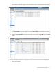
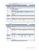
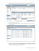
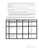
Table Of Contents
- HP Virtual Connect for c-Class BladeSystem Version 4.01 User Guide
- Abstract
- Notice
- Contents
- Introduction
- HP Virtual Connect Manager
- Virtual Connect domains
- Understanding Virtual Connect domains
- Managing domains
- Managing SNMP
- Viewing the system log
- Managing SSL configuration
- HP BladeSystem c-Class enclosures
- Virtual Connect users and roles
- Understanding VC administrative roles
- Managing users
- Local Users screen
- Configuring LDAP, RADIUS, and TACACS+
- Minimum requirements
- LDAP Server Settings (LDAP Server) screen
- LDAP Server Settings (LDAP Groups) screen
- LDAP Server Settings (LDAP Certificate) screen
- RADIUS Settings (RADIUS Server) screen
- RADIUS Settings (RADIUS Groups) screen
- TACACS+ Settings screen
- Role Management (Role Authentication Order) screen
- Role Management (Role Operations) screen
- Virtual Connect networks
- Understanding networks and shared uplink sets
- Managing networks
- Network Access Groups screen
- Define Network Access Group screen
- Ethernet Settings (Port Monitoring) screen
- Ethernet Settings (Advanced Settings) screen
- Quality of Service
- IGMP Settings (IGMP Configuration) screen
- IGMP Settings (Multicast Filter Set) screen
- Define Ethernet Network screen
- Ethernet Networks (External Connections) screen
- Ethernet Networks (Server Connections) screen
- Managing shared uplink sets
- Virtual Connect fabrics
- Virtual Connect server profiles
- Understanding server profiles
- Managing MAC, WWN, and server virtual ID settings
- Managing server profiles
- Define Server Profile screen
- Creating FCoE HBA connections for a BL890c i4
- Limited Ethernet connections when using HP Virtual Connect Flex-10/10D modules
- Creating iSCSI connections
- Flex-10 iSCSI connections
- Define Server Profile screen (multiple enclosures)
- Multiple network connections for a server port
- Defining server VLAN mappings
- Fibre Channel boot parameters
- Server Profiles screen
- Edit Server Profile screen
- Assigning a server profile with FCoE connections to an HP ProLiant BL680c G7 Server Blade
- Unassigning a server profile with FCoE connections to an HP ProLiant BL680c G7 Server Blade and deleting the SAN fabric
- General requirements for adding FC or FCoE connections
- Define Server Profile screen
- Virtual Connect and Insight Control Server Deployment
- Virtual Connect modules
- Firmware updates
- Stacking Links screen
- Throughput Statistics screen
- Enclosure Information screen
- Enclosure Status screen
- Interconnect Bays Status and Summary screen
- Causes for INCOMPATIBLE status
- Ethernet Bay Summary (General Information) screen
- Ethernet Bay Summary (Uplink Port Information) screen
- Ethernet Bay Summary (Server Port Information) screen
- Ethernet Bay Summary (MAC Address Table) screen
- Ethernet Bay Summary (IGMP Multicast Groups) screen
- Ethernet Bay Summary (Name Server) screen
- Ethernet Port Detailed Statistics screen
- FC Port Detailed Statistics screen
- FC Bay Summary screen
- Interconnect Bay Overall Status icon definitions
- Interconnect Bay OA Reported Status icon definitions
- Interconnect Bay VC Status icon definitions
- Interconnect Bay OA Communication Status icon definitions
- Server Bays Summary screen
- Server Bay Status screen
- Port status conditions
- Interconnect module removal and replacement
- Virtual Connect modules
- Upgrading to an HP Virtual Connect 8Gb 24-Port FC Module
- Upgrading to an HP Virtual Connect 8Gb 20-Port FC Module
- Upgrading or removing an HP Virtual Connect Flex-10, HP Virtual Connect FlexFabric, or HP Virtual Connect Flex-10/10D module
- Upgrading to an HP Virtual Connect FlexFabric module from a VC-FC module
- Onboard Administrator modules
- Maintenance and troubleshooting
- Appendix: Using Virtual Connect with nPartitions
- Support and other resources
- Acronyms and abbreviations
- Documentation feedback
- Index

Virtual Connect server profiles 220
• When a profile is added, the FC/FCoE connections initially displayed are based on the FC/FCoE
module configuration in the domain. A pair of horizontally adjacent FC/FCoE-capable modules has
two connections.
• Connections can only be added or removed from the bottom. You can only add or delete connections
at the end of the list.
• You can remove connections at any time (one at a time, from the bottom).
• If the existing profile connections do not match the current FC/FCoE module configurations, the add
operation is not allowed.
• The current maximum number of per server profile FC/FCoE connections mapped to the same I/O bay
is four, unless you are using the HP Integrity BL890c i4 Server Blade.
o When FlexFabric modules exist in I/O bays 1 and 2, there can be an additional eight FCoE
connections that will get mapped to LOMs 3 and 4 on the blades in an Integrity BL890c i4 server.
The BL890c i4 server has CNA LOMs, which enable two FCoE connections to I/O bay 1 (from
LOMs 1 and 3) and two FCoE connections to I/O bay 2 (from LOMs 2 and 4).
The following table lists several scenarios that describe how adding FC/FCoE connections affects an existing
profile. The scenarios are true for FC module configurations and FC modules, as well as FCoE module
configurations and FCoE-capable modules.
Scenario Description Existing profile
connections
Current FC module
configurations
Adding profile connections
1
Start with modules in Bays 3
and 4, create a profile, then
edit the profile and add
connections.
Port Connected to
1 Bay 3
2 Bay 4
— —
Bay 3 Bay 4
— —
— —
Port Connected to
1 Bay 3
2 Bay 4
3 Bay 3
4 Bay 4
Add connection, 2 times
2
Start with modules in Bays
3–6, create a profile, then
edit the profile and add
connections.
Port Connected to
1 Bay 3
2 Bay 4
3 Bay 5
4 Bay 6
— —
Bay 3 Bay 4
Bay 5 Bay 6
— —
Port Connected to
1 Bay 3
2 Bay 4
3 Bay 5
4 Bay 6
5 Bay 3
6 Bay 4
7 Bay 5
8 Bay 6
Add connection, 4 times
3
Start with modules in Bays 3
and 4, create a profile,
install modules into Bays 5
and 6, then edit the profile
and add connections.
Port Connected to
1 Bay 3
2 Bay 4
— —
Bay 3 Bay 4
Bay 5 Bay 6
— —
Port Connected to
1 Bay 3
2 Bay 4
3 Bay 5
4 Bay 6
Add connection, 2 times