
HP Virtual Connect for c-Class BladeSystem Version 4.01 User Guide
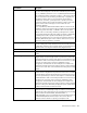


Table Of Contents
- HP Virtual Connect for c-Class BladeSystem Version 4.01 User Guide
- Abstract
- Notice
- Contents
- Introduction
- HP Virtual Connect Manager
- Virtual Connect domains
- Understanding Virtual Connect domains
- Managing domains
- Managing SNMP
- Viewing the system log
- Managing SSL configuration
- HP BladeSystem c-Class enclosures
- Virtual Connect users and roles
- Understanding VC administrative roles
- Managing users
- Local Users screen
- Configuring LDAP, RADIUS, and TACACS+
- Minimum requirements
- LDAP Server Settings (LDAP Server) screen
- LDAP Server Settings (LDAP Groups) screen
- LDAP Server Settings (LDAP Certificate) screen
- RADIUS Settings (RADIUS Server) screen
- RADIUS Settings (RADIUS Groups) screen
- TACACS+ Settings screen
- Role Management (Role Authentication Order) screen
- Role Management (Role Operations) screen
- Virtual Connect networks
- Understanding networks and shared uplink sets
- Managing networks
- Network Access Groups screen
- Define Network Access Group screen
- Ethernet Settings (Port Monitoring) screen
- Ethernet Settings (Advanced Settings) screen
- Quality of Service
- IGMP Settings (IGMP Configuration) screen
- IGMP Settings (Multicast Filter Set) screen
- Define Ethernet Network screen
- Ethernet Networks (External Connections) screen
- Ethernet Networks (Server Connections) screen
- Managing shared uplink sets
- Virtual Connect fabrics
- Virtual Connect server profiles
- Understanding server profiles
- Managing MAC, WWN, and server virtual ID settings
- Managing server profiles
- Define Server Profile screen
- Creating FCoE HBA connections for a BL890c i4
- Limited Ethernet connections when using HP Virtual Connect Flex-10/10D modules
- Creating iSCSI connections
- Flex-10 iSCSI connections
- Define Server Profile screen (multiple enclosures)
- Multiple network connections for a server port
- Defining server VLAN mappings
- Fibre Channel boot parameters
- Server Profiles screen
- Edit Server Profile screen
- Assigning a server profile with FCoE connections to an HP ProLiant BL680c G7 Server Blade
- Unassigning a server profile with FCoE connections to an HP ProLiant BL680c G7 Server Blade and deleting the SAN fabric
- General requirements for adding FC or FCoE connections
- Define Server Profile screen
- Virtual Connect and Insight Control Server Deployment
- Virtual Connect modules
- Firmware updates
- Stacking Links screen
- Throughput Statistics screen
- Enclosure Information screen
- Enclosure Status screen
- Interconnect Bays Status and Summary screen
- Causes for INCOMPATIBLE status
- Ethernet Bay Summary (General Information) screen
- Ethernet Bay Summary (Uplink Port Information) screen
- Ethernet Bay Summary (Server Port Information) screen
- Ethernet Bay Summary (MAC Address Table) screen
- Ethernet Bay Summary (IGMP Multicast Groups) screen
- Ethernet Bay Summary (Name Server) screen
- Ethernet Port Detailed Statistics screen
- FC Port Detailed Statistics screen
- FC Bay Summary screen
- Interconnect Bay Overall Status icon definitions
- Interconnect Bay OA Reported Status icon definitions
- Interconnect Bay VC Status icon definitions
- Interconnect Bay OA Communication Status icon definitions
- Server Bays Summary screen
- Server Bay Status screen
- Port status conditions
- Interconnect module removal and replacement
- Virtual Connect modules
- Upgrading to an HP Virtual Connect 8Gb 24-Port FC Module
- Upgrading to an HP Virtual Connect 8Gb 20-Port FC Module
- Upgrading or removing an HP Virtual Connect Flex-10, HP Virtual Connect FlexFabric, or HP Virtual Connect Flex-10/10D module
- Upgrading to an HP Virtual Connect FlexFabric module from a VC-FC module
- Onboard Administrator modules
- Maintenance and troubleshooting
- Appendix: Using Virtual Connect with nPartitions
- Support and other resources
- Acronyms and abbreviations
- Documentation feedback
- Index

Virtual Connect modules 243
Port Statistic Description
EtherStatsPkts65to127Octets
The total number of packets (including bad packets) received that were
between 65 and 127 octets in length inclusive (excluding framing bits, but
including FCS octets)
EtherStatsPkts128to255Octets
The total number of packets (including bad packets) received that were
between 128 and 255 octets in length inclusive (excluding framing bits,
but including FCS octets)
EtherStatsPkts256to511Octets
The total number of packets (including bad packets) received that were
between 256 and 511 octets in length inclusive (excluding framing bits,
but including FCS octets)
EtherStatsPkts512to1023Octets
The total number of packets (including bad packets) received that were
between 512 and 1023 octets in length inclusive (excluding framing bits,
but including FCS octets)
EtherStatsPkts1024to1518Octets
The total number of packets (including bad packets) received that were
between 1024 and 1518 octets in length inclusive (excluding framing
bits, but including FCS octets)
EtherStatsOversizePkts
The total number of packets received that were longer than 1518 octets
(excluding framing bits, but including FCS octets) and were otherwise
well-formed
EtherStatsJabbers
The total number of packets received that were longer than 1518 octets
(excluding framing bits, but including FCS octets), and had either a bad
FCS with an integral number of octets (FCS Error) or a bad FCS with a
non-integral number of octets (Alignment Error). This definition of jabber is
different than the definition in IEEE-802.3 section 8.2.1.5 (10BASE5) and
section 10.3.1.4 (10BASE2). These documents define jabber as the
condition where any packet exceeds 20 ms. The allowed range to detect
jabber is between 20 ms and 150 ms.
EtherStatsOctets*
The total number of octets of data (including those in bad packets)
received on the FCS octets). This object can be used as a reasonable
estimate of Ethernet utilization. If greater precision is required, the
StatsPkts and StatsOctets objects should be sampled before and after a
common interval. The differences in the sampled values are Pkts and
Octets, respectively, and the number of seconds in the interval is Interval.
These values are used to calculate the Utilization as follows: Utilization =
[(Pkts * (9.6 + 6.4) + (Octets * .8)) / (Interval * 10,000)]. The result of this
equation is the value Utilization which is the percent utilization of the
Ethernet segment on a scale of 0 to 100 percent.
EtherStatsPkts*
The total number of packets (including bad packets, broadcast packets,
and multicast packets) received