
HP Virtual Connect for c-Class BladeSystem Version 4.01 User Guide
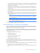


Table Of Contents
- HP Virtual Connect for c-Class BladeSystem Version 4.01 User Guide
- Abstract
- Notice
- Contents
- Introduction
- HP Virtual Connect Manager
- Virtual Connect domains
- Understanding Virtual Connect domains
- Managing domains
- Managing SNMP
- Viewing the system log
- Managing SSL configuration
- HP BladeSystem c-Class enclosures
- Virtual Connect users and roles
- Understanding VC administrative roles
- Managing users
- Local Users screen
- Configuring LDAP, RADIUS, and TACACS+
- Minimum requirements
- LDAP Server Settings (LDAP Server) screen
- LDAP Server Settings (LDAP Groups) screen
- LDAP Server Settings (LDAP Certificate) screen
- RADIUS Settings (RADIUS Server) screen
- RADIUS Settings (RADIUS Groups) screen
- TACACS+ Settings screen
- Role Management (Role Authentication Order) screen
- Role Management (Role Operations) screen
- Virtual Connect networks
- Understanding networks and shared uplink sets
- Managing networks
- Network Access Groups screen
- Define Network Access Group screen
- Ethernet Settings (Port Monitoring) screen
- Ethernet Settings (Advanced Settings) screen
- Quality of Service
- IGMP Settings (IGMP Configuration) screen
- IGMP Settings (Multicast Filter Set) screen
- Define Ethernet Network screen
- Ethernet Networks (External Connections) screen
- Ethernet Networks (Server Connections) screen
- Managing shared uplink sets
- Virtual Connect fabrics
- Virtual Connect server profiles
- Understanding server profiles
- Managing MAC, WWN, and server virtual ID settings
- Managing server profiles
- Define Server Profile screen
- Creating FCoE HBA connections for a BL890c i4
- Limited Ethernet connections when using HP Virtual Connect Flex-10/10D modules
- Creating iSCSI connections
- Flex-10 iSCSI connections
- Define Server Profile screen (multiple enclosures)
- Multiple network connections for a server port
- Defining server VLAN mappings
- Fibre Channel boot parameters
- Server Profiles screen
- Edit Server Profile screen
- Assigning a server profile with FCoE connections to an HP ProLiant BL680c G7 Server Blade
- Unassigning a server profile with FCoE connections to an HP ProLiant BL680c G7 Server Blade and deleting the SAN fabric
- General requirements for adding FC or FCoE connections
- Define Server Profile screen
- Virtual Connect and Insight Control Server Deployment
- Virtual Connect modules
- Firmware updates
- Stacking Links screen
- Throughput Statistics screen
- Enclosure Information screen
- Enclosure Status screen
- Interconnect Bays Status and Summary screen
- Causes for INCOMPATIBLE status
- Ethernet Bay Summary (General Information) screen
- Ethernet Bay Summary (Uplink Port Information) screen
- Ethernet Bay Summary (Server Port Information) screen
- Ethernet Bay Summary (MAC Address Table) screen
- Ethernet Bay Summary (IGMP Multicast Groups) screen
- Ethernet Bay Summary (Name Server) screen
- Ethernet Port Detailed Statistics screen
- FC Port Detailed Statistics screen
- FC Bay Summary screen
- Interconnect Bay Overall Status icon definitions
- Interconnect Bay OA Reported Status icon definitions
- Interconnect Bay VC Status icon definitions
- Interconnect Bay OA Communication Status icon definitions
- Server Bays Summary screen
- Server Bay Status screen
- Port status conditions
- Interconnect module removal and replacement
- Virtual Connect modules
- Upgrading to an HP Virtual Connect 8Gb 24-Port FC Module
- Upgrading to an HP Virtual Connect 8Gb 20-Port FC Module
- Upgrading or removing an HP Virtual Connect Flex-10, HP Virtual Connect FlexFabric, or HP Virtual Connect Flex-10/10D module
- Upgrading to an HP Virtual Connect FlexFabric module from a VC-FC module
- Onboard Administrator modules
- Maintenance and troubleshooting
- Appendix: Using Virtual Connect with nPartitions
- Support and other resources
- Acronyms and abbreviations
- Documentation feedback
- Index

Appendix: Using Virtual Connect with nPartitions 277
Appendix: Using Virtual Connect with nPartitions
Understanding nPartitions
The HP BL870c i4 or HP BL980c i4 servers can be partitioned into separate, smaller servers, called
nPartitions, using iLO. Each nPartition is treated identically to a server of comparable size and type. The set
of blades that are conjoined by a Blade Link is referred to as a Blade Link Domain. An nPartition must be
wholly contained within a blade link domain. The configuration of nPars is explained below.
A BL870c i4 can be configured as a single 2-blade server, or as two 1-blade partitions. If the BL870c i4 was
installed in device bays 1-2, each configuration would be represented in VC as follows:
• One 2-blade system (not an nPar) (AA)
o Bay 1-2 (HP Integrity BL870c i4)
• Two 1-blade nPars (AB)
o Bay 1 (HP Integrity BL870c i4 nPar)
o Bay 2 (HP Integrity BL870c i4 nPar)
A BL890c i4 can be configured in one of five ways. If the BL890c i4 is installed in device bays 1-4, each
configuration would be represented in VC as follows:
• One 4-blade system (not an nPar) (AAAA)
o Bays 1-4 (HP Integrity BL890c i4)
• Two 2-blade nPars (AACC)
o Bays 1-2 (HP Integrity BL890c i4 nPar)
o Bays 3-4 (HP Integrity BL890c i4 nPar)
• One 2-blade nPar and two 1-blade nPartitions (AACD)
o Bays 1-2 (HP Integrity BL890c i4 nPar)
o Bay 3 (HP Integrity BL890c i4 nPar)
o Bay 4 (HP Integrity BL890c i4 nPar)
• Two 1-blade nPars and one 2-blade nPartition (ABCC)
o Bay 1 (HP Integrity BL890c i4 nPar)
o Bay 2 (HP Integrity BL890c i4 nPar)
o Bays 3-4 (HP Integrity BL890c i4 nPar)
• Four 1-blade nPars (ABCD)
o Bay 1 (HP Integrity BL890c i4 nPar)
o Bay 2 (HP Integrity BL890c i4 nPar)
o Bay 3 (HP Integrity BL890c i4 nPar)
o Bay 4 (HP Integrity BL890c i4 nPar)