
HP Virtual Connect for c-Class BladeSystem Version 4.01 User Guide
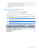
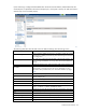
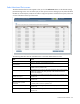
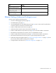
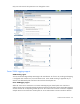
Table Of Contents
- HP Virtual Connect for c-Class BladeSystem Version 4.01 User Guide
- Abstract
- Notice
- Contents
- Introduction
- HP Virtual Connect Manager
- Virtual Connect domains
- Understanding Virtual Connect domains
- Managing domains
- Managing SNMP
- Viewing the system log
- Managing SSL configuration
- HP BladeSystem c-Class enclosures
- Virtual Connect users and roles
- Understanding VC administrative roles
- Managing users
- Local Users screen
- Configuring LDAP, RADIUS, and TACACS+
- Minimum requirements
- LDAP Server Settings (LDAP Server) screen
- LDAP Server Settings (LDAP Groups) screen
- LDAP Server Settings (LDAP Certificate) screen
- RADIUS Settings (RADIUS Server) screen
- RADIUS Settings (RADIUS Groups) screen
- TACACS+ Settings screen
- Role Management (Role Authentication Order) screen
- Role Management (Role Operations) screen
- Virtual Connect networks
- Understanding networks and shared uplink sets
- Managing networks
- Network Access Groups screen
- Define Network Access Group screen
- Ethernet Settings (Port Monitoring) screen
- Ethernet Settings (Advanced Settings) screen
- Quality of Service
- IGMP Settings (IGMP Configuration) screen
- IGMP Settings (Multicast Filter Set) screen
- Define Ethernet Network screen
- Ethernet Networks (External Connections) screen
- Ethernet Networks (Server Connections) screen
- Managing shared uplink sets
- Virtual Connect fabrics
- Virtual Connect server profiles
- Understanding server profiles
- Managing MAC, WWN, and server virtual ID settings
- Managing server profiles
- Define Server Profile screen
- Creating FCoE HBA connections for a BL890c i4
- Limited Ethernet connections when using HP Virtual Connect Flex-10/10D modules
- Creating iSCSI connections
- Flex-10 iSCSI connections
- Define Server Profile screen (multiple enclosures)
- Multiple network connections for a server port
- Defining server VLAN mappings
- Fibre Channel boot parameters
- Server Profiles screen
- Edit Server Profile screen
- Assigning a server profile with FCoE connections to an HP ProLiant BL680c G7 Server Blade
- Unassigning a server profile with FCoE connections to an HP ProLiant BL680c G7 Server Blade and deleting the SAN fabric
- General requirements for adding FC or FCoE connections
- Define Server Profile screen
- Virtual Connect and Insight Control Server Deployment
- Virtual Connect modules
- Firmware updates
- Stacking Links screen
- Throughput Statistics screen
- Enclosure Information screen
- Enclosure Status screen
- Interconnect Bays Status and Summary screen
- Causes for INCOMPATIBLE status
- Ethernet Bay Summary (General Information) screen
- Ethernet Bay Summary (Uplink Port Information) screen
- Ethernet Bay Summary (Server Port Information) screen
- Ethernet Bay Summary (MAC Address Table) screen
- Ethernet Bay Summary (IGMP Multicast Groups) screen
- Ethernet Bay Summary (Name Server) screen
- Ethernet Port Detailed Statistics screen
- FC Port Detailed Statistics screen
- FC Bay Summary screen
- Interconnect Bay Overall Status icon definitions
- Interconnect Bay OA Reported Status icon definitions
- Interconnect Bay VC Status icon definitions
- Interconnect Bay OA Communication Status icon definitions
- Server Bays Summary screen
- Server Bay Status screen
- Port status conditions
- Interconnect module removal and replacement
- Virtual Connect modules
- Upgrading to an HP Virtual Connect 8Gb 24-Port FC Module
- Upgrading to an HP Virtual Connect 8Gb 20-Port FC Module
- Upgrading or removing an HP Virtual Connect Flex-10, HP Virtual Connect FlexFabric, or HP Virtual Connect Flex-10/10D module
- Upgrading to an HP Virtual Connect FlexFabric module from a VC-FC module
- Onboard Administrator modules
- Maintenance and troubleshooting
- Appendix: Using Virtual Connect with nPartitions
- Support and other resources
- Acronyms and abbreviations
- Documentation feedback
- Index

Virtual Connect networks 97
when creating or editing a profile. When this check box is selected, server network connections can only be
selected from a single shared uplink set.
When the 'Force server connections to use same VLAN mappings as shared uplink sets' check box is not
selected, server network connections can be selected from any VC Ethernet network and the external VLAN
ID mappings can be manually edited. However, administrators must ensure that no server connection VLAN
ID conflict exists.
The 'Force server connections to use the same VLAN mappings as shared uplink sets' check box can be
selected if no server profile connections are assigned to multiple networks that are not linked to a shared
uplink set.
VLAN Capacity
When creating a new domain in VC 3.70 or higher, the option to select Legacy VLAN Capacity mode is
disabled and reverting from Expanded VLAN Capacity mode back to Legacy VLAN Capacity mode is not
allowed. Domains that are upgraded from VC 3.30 that contain the Legacy VLAN Capacity mode setting are
upgraded to Expanded VLAN Capacity mode as part of the VC 3.70 or higher firmware upgrade. To
maintain compatibility with VC 3.30 domains that have Legacy VLAN Capacity mode enabled, the VCM CLI
maintains the current functionality for the VLAN mode. This also allows the use of existing scripts that
manipulate the VLAN capacity.
Expanded VLAN Capacity mode allows up to 1000 VLANs per domain. The number of VLANs per shared
uplink set is restricted to 1000. In addition, up to 162 VLANs are allowed per physical server port, with no
restriction on how those VLANs are distributed among the server connections mapped to the same physical
server port. There is also a limit of 162 VLANs per server connection. However, you must take care not to
exceed the limit per physical server port. For example, if you configure 150 VLAN mappings for a server
connection (FlexNIC-a) of a Flex-10 physical server port, then you can only map 12 VLANs to the remaining
three server connections (FlexNIC-b, FlexNIC-c, and FlexNIC-d) of the same physical server port. If you
exceed the 162 VLAN limit, the physical server port is disabled and the four server connections are marked
as Failed.
Multiple Networks Link Speed Settings
When using mapped VLAN tags (multiple networks over a single link), these settings are used for the overall
link speed control. Select the checkbox next to each item to set the value.
These settings affect only newly created profiles.
Versions of VC prior to v4.01 used the "preferred speed" to control bandwidth allocation. When existing
profiles are upgraded to VC v4.01, the "maximum speed" from the network is set automatically on the
connection. If no maximum speed was configured prior to the upgrade, then the maximum speed will be 10
Gb for Ethernet connections and 8Gb for FCoE connections. The pre-4.01 behavior can be retained by
setting "maximum speed" to the same value as "preferred speed".
IMPORTANT: Depending on the NIC firmware versions in use, you might need to upgrade the
NIC firmware for these speed enforcement settings to work correctly.
To change these settings:
1. Click the selection box, and then select a setting (100Mb to 10Gb):
o Set preferred connection speed. This value is the default speed for server profile connections
mapped to this network. The server administrator can increase or decrease this setting on an
individual profile connection.