
HP Virtual Connect Manager Command Line Interface for c-Class BladeSystem Version 3.70/3.75 User Guide

Configuring the Virtual Connect domain using the CLI 152
Virtual Connect only transmits MAC Cache update frames on VLANs that have been configured in the VC
domain. The update frames are VLAN tagged appropriately for networks defined on shared uplink sets. For
dedicated networks, only untagged update frames are generated, regardless of whether or not VLAN
Tunneling is enabled. In a VLAN tunnel, all customer VLAN tags pass through Virtual Connect transparently.
Virtual Connect does not examine nor record VLAN tag information in tunneled networks; therefore, it cannot
generate tagged update frames.
IMPORTANT: Be sure to set switches to allow MAC addresses to move from one port to another
without waiting for an expiration period or causing a lock out.
Always enable the "spanning tree portfast" feature to allow the switch port to bypass the
"listening" and "learning" stages of spanning tree and quickly transition to the "forwarding"
stage, allowing edge devices to immediately begin communication on the network.
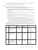
Configuring network loop protection settings
To enable network loop protection, use the set loop-protect command:
>set loop-protect Enabled=true
To reset network loop protection, use the reset loop-protect command:
>reset loop-protect
To avoid network loops, Virtual Connect first verifies that only one active uplink exists per network from the
Virtual Connect domain to the external Ethernet switching environment. Second, Virtual Connect makes sure
that no network loops are created by the stacking links between Virtual Connect modules.
• One active link—A VC uplink set can include multiple uplink ports. To prevent a loop with broadcast
traffic coming in one uplink and going out another, only one uplink or uplink LAG is active at a time. The
uplink or LAG with the greatest bandwidth should be selected as the active uplink. If the active uplink
loses the link, then the next best uplink is made active.
• No loops through stacking links—If multiple VC-Enet modules are used, they are interconnected using
stacking links, which might appear as an opportunity for loops within the VC environment. For each
individual network in the Virtual Connect environment, VC blocks certain stacking links to ensure that
each network has a loop-free topology.
Enhanced network loop protection detects loops on downlink ports, which can be a Flex-10 logical port or
physical port. The feature applies to Flex-10 logical function if the Flex-10 port is operating under the control
of DCC protocol. If DCC is not available, the feature applies to a physical downlink port.
Enhanced network loop protection uses two methods to detect loops:
• It periodically injects a special probe frame into the VC domain and monitors downlink ports for the
looped back probe frame. If this special probe frame is detected on downlink ports, the port is
considered to cause the loop condition.
• It monitors and intercepts common loop detection frames used in other switches. In network
environments where the upstream switches send loop detection frames, the VC Enet modules must
ensure that any downlink loops do not cause these frames to be sent back to the uplink ports. Even
though VC probe frames ensure loops are detected, there is a small time window depending on the
probe frame transmission interval in which the loop detection frames from the external switch might loop
through down link ports and reach uplink ports. By intercepting the external loop detection frames on
downlinks, the possibility of triggering loop protection on the upstream switch is eliminated. When
network loop protection is enabled, VC-Enet modules intercept the following types of loop detection
frames:
o PVST+ BPDUs