
HP Virtual Connect Manager Command Line Interface for c-Class BladeSystem Version 4.20 User Guide


Configuring the Virtual Connect domain using the CLI 193
8
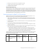
Start with modules in Bays
5–8, create a profile, install
modules into Bays 3 and 4,
then edit the profile.
Port Connected to
1 Bay 5
2 Bay 6
4 Bay 7
5 Bay 8
— —
Bay 3 Bay 4
Bay 5 Bay 6
Bay 7 Bay 8
Add connection is disallowed
because the current FC module
configurations do not match
the existing connections in the
profile.
To make this profile useful,
remove the two connections,
save the profile, and then
begin adding connections.
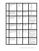
9
Start with FCoE-capable
modules in Bays 1 and 2,
then create a profile and
add connections.
Port Connected to
1 Bay 1
2 Bay 2
Bay 1 Bay 2
— —
— —
— —
Port Connected to
1 Bay 1
2 Bay 2
3 Bay 1
4 Bay 2
5 Bay 1
6 Bay 2
7 Bay 1
8 Bay 2
Add connection, 6 times*
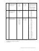
10
Start with 8 FCoE-capable
modules, then create a
profile and add connections.
Port Connected to
1 Bay 1
2 Bay 2
3 Bay 3
4 Bay 4
5 Bay 5
6 Bay 6
7 Bay 7
8 Bay 8
Bay 1 Bay 2
Bay 3 Bay 4
Bay 5 Bay 6
Bay 7 Bay 8
Port Connected to
1 Bay 1
2 Bay 2
3 Bay 3
4 Bay 4
5 Bay 5
6 Bay 6
7 Bay 7
8 Bay 8
9 Bay 1
10 Bay 2
11 Bay 3
12 Bay 4
13 Bay 5
14 Bay 6
15 Bay 7
16 Bay 8
17 Bay 1
18 Bay 2
19 Bay 3**
20 Bay 4**
21 Bay 5**
22 Bay 6**
23 Bay 7**
24 Bay 8**
25 Bay 1
26 Bay 2
Add connection, 18 times
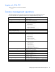
* Using the BL890c i4 server blade, an additional eight connections can still be added. Each pair is connect to bays 1
and 2. The first four pairs of entries are mapped to LOM 1 and LOM 2 on each blade, and the last four pairs of entries
are mapped to LOM 3 and LOM 4 on each blade.
** Not mapped