
FCoE Cookbook for HP Virtual Connect Version 4.20 Firmware Enhancements May 2014
119
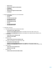
FCoE VLANs should be dedicated to FCoE traffic (i.e. it should not carry IP traffic).
You must enable FCoE for the same VLAN and map this VLAN to the same VSAN end-to-end.
Interfaces connecting to VC must be configured as trunk ports and STP edge ports.
For each Blade server, one vfc interface with MAC Binding must be defined because Virtual Connect is running in FIP
snooping mode.
FC and FCoE-based Storage devices connected to the Nexus switch are supported.
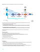
Virtual Connect configuration
Before you configure the upstream switches, Virtual Connect requires the creation of an Active/Active configuration of
two converged Shared Uplink Sets (SUS). Refer to the Virtual Connect configuration section.
If you need to improve the Ethernet traffic service level control, refer to the Quality of Service in the Virtual Connect
Domain section.
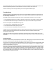
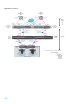
HP 5900 and Nexus Switch configuration
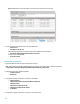
Details about the HP 5900 configuration:
NPV mode is used.
Interfaces XGE1/0/12-14 are connected to the VC modules thought FCoE using a bridge aggregation BAGG 20.
Interfaces XGE1/0/16-17 are connected to the Nexus switches thought FCoE using a bridge aggregation BAGG 30
(VNP_Ports).
VLAN IDs 200/300 and 201/301 are used for the FCoE networks.
VSAN 200/300 and 201/301 are used for the FCoE traffic.
VLAN 200 maps to VSAN 200, VLAN 300 to VSAN 300, VLAN 201 to VSAN 201 and VLAN 301 to VSAN 301
VLAN IDs 1, 10 and 20 are the standard Ethernet networks (non-FCoE networks).
The virtual Fibre Channel interfaces vfc 1 bind to the MAC addresses of the first Blade server.
The virtual Fibre Channel interfaces vfc 2 bind to the MAC addresses of the second Blade server.
The virtual Fibre Channel interfaces vfc 1000 bind to the bridge aggregation BAGG 30 connected to the Nexus.
Details about the Nexus 5xxx configuration:
FCF mode is used.
Interfaces Eth1/11-12 are connected to the HP 5900 switches thought FCoE using a port channel po300 (VNP_Ports).
Interfaces eth1/1 are connected to an FCoE-based storage device (EVA).
Interfaces eth1/17 are connected to the datacenter LAN.
Interfaces fc2/1 are directly connected to a FC-based storage device (3PAR).
VLAN IDs 200/300 and 201/301 are used for the FCoE networks.
VSAN 200/300 and 201/301 are used for the FCoE traffic.
VLAN 200 maps to VSAN 200, VLAN 300 to VSAN 300, VLAN 201 to VSAN 201 and VLAN 301 to VSAN 301
VLAN IDs 1, 10 and 20 are the standard Ethernet networks (non-FCoE networks).
The virtual Fibre Channel interfaces vfc 1000 bind to the port channel po300 connected to the 5900AF.
The virtual Fibre Channel interfaces vfc 2007 bind to eth1/1 for the EVA FCoE-based storage array.
The EVA is connected to VSAN 30x and the 3PAR is connected to VSANs 20x.