
FCoE Cookbook for HP Virtual Connect Version 4.20 Firmware Enhancements May 2014


135
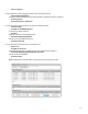
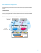
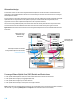
Virtual Connect configuration
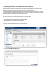
Extending FCoE through FIP Snooping with HP Virtual Connect requires the creation of an Active/Active configuration of
two converged Shared Uplink Sets (SUS) which contain at least one FCoE network and optionally associated non-FCoE
network(s).
Standard design
With the Virtual Connect standard design, the upstream network switches connect to each Virtual Connect module
through two separate Converged Shared Uplink Sets, providing an Active/Active configuration. The use of multiple FCoE
uplink ports on each VC module is highly recommended to aggregate the FCoE links to increase the high availability and
to create enough subscription.
Figure 37: Standard Virtual Connect Active-Active Converged Shared Uplink Sets scenario
VC Module bay 2
Active
TOR Switch 2
FlexHBA FlexNIC
FlexNIC
FlexNIC
VC Domain
VC Module bay 1
TOR Switch 1
Active
FlexHBA
FlexNIC FlexNIC
FlexNIC
vSwitch or NIC Teaming
FlexFabric
Adapter Port 1
FlexFabric
Adapter Port 2
Multi Pathing
Nexus 5xxx Series
ToR Switch using
Fabric Mode
X1 X1
X2 X2
DCB-1
DCB-2
802.1q
802.3ad
802.1q
802.3ad
Lossless
Ethernet
Network
Converged
Shared Uplink Sets
Blade Server
FcoE
FcoE