
FCoE Cookbook for HP Virtual Connect Version 4.20 Firmware Enhancements May 2014

71
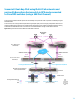
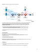
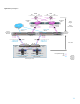
Configure the Fibre Channel interfaces connected to the Brocade-B SAN switch:
o interface fc 2/1
o switchport description NP Port connected to Brocade-B
o switchport mode np
o no shutdown
Note: The upstream Brocade SAN switch needs to be NPIV-enabled. To enable NPIV on port 13 on the Brocade
SAN switch, enter the following command:
portCfgNPIVPort 13 1 {Where 1 indicates that NPIV is enabled}
# if port 13 is a 8G port, it is necessary to add:
portCfgFillWord 13 3 {Only applicable to 8G-capable ports}
For more information about NPIV support for your Fibre Channel switch, refer to the switch vendor
documentation.
Associate each VLAN with a VSAN for each FCoE networks:
o vlan 201
o fcoe vsan 201
o vlan 301
o fcoe vsan 301
Note: Enabling FCoE on VLAN 1 is not supported.
Note: Make sure that these VLAN IDs are the same as the second Shared Uplink Set FCoE’s VLAN IDs in VCM.
Create a port channel between the VC module Bay 2 and the Nexus switch B with eth1/5 and eth1/6 with the same
LACP Timer as defined by default in the Virtual Connect Domain, eth1/5 and eth1/6 can be used because both are
mapped to the same UPC (i.e. UPC#1) on Nexus 5010 (for more information see Appendix A):
o interface ethernet 1/5-6
o channel-group 200 mode active
o lacp rate fast
Create the VLANs for the IP traffic:
o vlan 1,10,20
Create a trunk on the port channel interface to pass the FCoE VLANs 201 and 301 and Ethernet traffic (VLAN 1,10,20):
o interface port-channel 200
o description FCoE Port Channel to VC-Bay2-X3/X4
o switchport mode trunk
o switchport trunk allowed vlan 1,10,20,201,301
o spanning-tree port type edge trunk
Create a virtual Fibre Channel interface for the first Blade server and bind it to the MAC address of its FCoE adapter:
o interface vfc 2005
o description vfc for server-1
o bind mac-address 00:17:a4:77:b8:eb
o no shutdown