
HP Virtual Connect for c-Class BladeSystem Version 4.01 User Guide
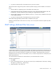
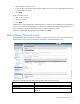

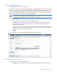
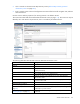
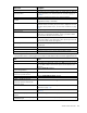
Table Of Contents
- HP Virtual Connect for c-Class BladeSystem Version 4.01 User Guide
- Abstract
- Notice
- Contents
- Introduction
- HP Virtual Connect Manager
- Virtual Connect domains
- Understanding Virtual Connect domains
- Managing domains
- Managing SNMP
- Viewing the system log
- Managing SSL configuration
- HP BladeSystem c-Class enclosures
- Virtual Connect users and roles
- Understanding VC administrative roles
- Managing users
- Local Users screen
- Configuring LDAP, RADIUS, and TACACS+
- Minimum requirements
- LDAP Server Settings (LDAP Server) screen
- LDAP Server Settings (LDAP Groups) screen
- LDAP Server Settings (LDAP Certificate) screen
- RADIUS Settings (RADIUS Server) screen
- RADIUS Settings (RADIUS Groups) screen
- TACACS+ Settings screen
- Role Management (Role Authentication Order) screen
- Role Management (Role Operations) screen
- Virtual Connect networks
- Understanding networks and shared uplink sets
- Managing networks
- Network Access Groups screen
- Define Network Access Group screen
- Ethernet Settings (Port Monitoring) screen
- Ethernet Settings (Advanced Settings) screen
- Quality of Service
- IGMP Settings (IGMP Configuration) screen
- IGMP Settings (Multicast Filter Set) screen
- Define Ethernet Network screen
- Ethernet Networks (External Connections) screen
- Ethernet Networks (Server Connections) screen
- Managing shared uplink sets
- Virtual Connect fabrics
- Virtual Connect server profiles
- Understanding server profiles
- Managing MAC, WWN, and server virtual ID settings
- Managing server profiles
- Define Server Profile screen
- Creating FCoE HBA connections for a BL890c i4
- Limited Ethernet connections when using HP Virtual Connect Flex-10/10D modules
- Creating iSCSI connections
- Flex-10 iSCSI connections
- Define Server Profile screen (multiple enclosures)
- Multiple network connections for a server port
- Defining server VLAN mappings
- Fibre Channel boot parameters
- Server Profiles screen
- Edit Server Profile screen
- Assigning a server profile with FCoE connections to an HP ProLiant BL680c G7 Server Blade
- Unassigning a server profile with FCoE connections to an HP ProLiant BL680c G7 Server Blade and deleting the SAN fabric
- General requirements for adding FC or FCoE connections
- Define Server Profile screen
- Virtual Connect and Insight Control Server Deployment
- Virtual Connect modules
- Firmware updates
- Stacking Links screen
- Throughput Statistics screen
- Enclosure Information screen
- Enclosure Status screen
- Interconnect Bays Status and Summary screen
- Causes for INCOMPATIBLE status
- Ethernet Bay Summary (General Information) screen
- Ethernet Bay Summary (Uplink Port Information) screen
- Ethernet Bay Summary (Server Port Information) screen
- Ethernet Bay Summary (MAC Address Table) screen
- Ethernet Bay Summary (IGMP Multicast Groups) screen
- Ethernet Bay Summary (Name Server) screen
- Ethernet Port Detailed Statistics screen
- FC Port Detailed Statistics screen
- FC Bay Summary screen
- Interconnect Bay Overall Status icon definitions
- Interconnect Bay OA Reported Status icon definitions
- Interconnect Bay VC Status icon definitions
- Interconnect Bay OA Communication Status icon definitions
- Server Bays Summary screen
- Server Bay Status screen
- Port status conditions
- Interconnect module removal and replacement
- Virtual Connect modules
- Upgrading to an HP Virtual Connect 8Gb 24-Port FC Module
- Upgrading to an HP Virtual Connect 8Gb 20-Port FC Module
- Upgrading or removing an HP Virtual Connect Flex-10, HP Virtual Connect FlexFabric, or HP Virtual Connect Flex-10/10D module
- Upgrading to an HP Virtual Connect FlexFabric module from a VC-FC module
- Onboard Administrator modules
- Maintenance and troubleshooting
- Appendix: Using Virtual Connect with nPartitions
- Support and other resources
- Acronyms and abbreviations
- Documentation feedback
- Index

Virtual Connect networks 116
Task Action
connection speed or maximum link
connection speed
see "Advanced Network Settings (on page 118)."
Set the Connection Mode
Select Auto or Failover. For a description of these modes, see "Defining
a network (on page 116)."
Set the LACP Timer
Select the duration for the LACP Timer ("LACP timer configuration" on
page 101).
Use a Shared Uplink Set for the external
port
Select the Use Shared Uplink Set checkbox, and then select the Shared
Uplink Set from the pull-down menu, and then enter the External VLAN
ID. This option is only available if there are Shared Uplink Sets defined.
Add an external uplink port to the
network
Use the cascading menu to select a port.
Change the uplink interface port speed
or disable the port
Click the pull-down box under Speed/Duplex, and then select a setting.
Delete an added port
Click the Delete link in the Action column, or left-click to select the line
item, right-click to display a pull-down menu, and then select Delete.
Add this network to Network Access
Groups
In the Network Access Groups field, begin typing the name of a Network
Access Group that should include this network. When the Network
Access Group name appears, select the name.
Remove this network from Network
Access Groups
In the Network Access Groups field, click the X next to the Network
Access Group name that should not be included.
Save changes
Click Apply.
Cancel without saving changes
Click Cancel.
Defining a network
To define a standalone network:
1. Enter a network name. The network name can be up to 64 characters in length (no spaces).
2. To add a color to the network, select a color from the Color pull-down menu. The network color is used
as a visual identifier for the network within VCM.
3. To add labels to the network, type a label in the Labels field, and then press Enter. Labels are used as
text-based identifiers for the network within VCM. Each label can contain up to 24 characters,
excluding spaces. Each network can have up to 16 labels.
4. Select whether to enable (checked) or disable (unchecked) Smart Link (on page 85).
The checkbox is not available until an uplink is added to the network.
5. Select whether to designate (checked) or not designate (unchecked) this network as a private network
("Private Networks" on page 85).
6. Select whether to enable (checked) or disable (unchecked) VLAN tunneling ("VLAN Tunneling Support"
on page 85).
7. If the network is to be used only internal to the Virtual Connect domain or enclosure, go to step 9 (do not
add any external ports).
8. Use the cascading menu to select a port, and then click Add to add one or more external ports. To
ensure a high availability connection, select two or more ports.
Only available ports are listed, displaying the current port link status.