
HP Virtual Connect for c-Class BladeSystem Version 4.01 User Guide
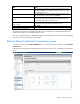
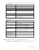
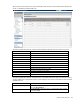
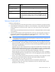
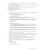
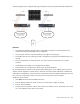
Table Of Contents
- HP Virtual Connect for c-Class BladeSystem Version 4.01 User Guide
- Abstract
- Notice
- Contents
- Introduction
- HP Virtual Connect Manager
- Virtual Connect domains
- Understanding Virtual Connect domains
- Managing domains
- Managing SNMP
- Viewing the system log
- Managing SSL configuration
- HP BladeSystem c-Class enclosures
- Virtual Connect users and roles
- Understanding VC administrative roles
- Managing users
- Local Users screen
- Configuring LDAP, RADIUS, and TACACS+
- Minimum requirements
- LDAP Server Settings (LDAP Server) screen
- LDAP Server Settings (LDAP Groups) screen
- LDAP Server Settings (LDAP Certificate) screen
- RADIUS Settings (RADIUS Server) screen
- RADIUS Settings (RADIUS Groups) screen
- TACACS+ Settings screen
- Role Management (Role Authentication Order) screen
- Role Management (Role Operations) screen
- Virtual Connect networks
- Understanding networks and shared uplink sets
- Managing networks
- Network Access Groups screen
- Define Network Access Group screen
- Ethernet Settings (Port Monitoring) screen
- Ethernet Settings (Advanced Settings) screen
- Quality of Service
- IGMP Settings (IGMP Configuration) screen
- IGMP Settings (Multicast Filter Set) screen
- Define Ethernet Network screen
- Ethernet Networks (External Connections) screen
- Ethernet Networks (Server Connections) screen
- Managing shared uplink sets
- Virtual Connect fabrics
- Virtual Connect server profiles
- Understanding server profiles
- Managing MAC, WWN, and server virtual ID settings
- Managing server profiles
- Define Server Profile screen
- Creating FCoE HBA connections for a BL890c i4
- Limited Ethernet connections when using HP Virtual Connect Flex-10/10D modules
- Creating iSCSI connections
- Flex-10 iSCSI connections
- Define Server Profile screen (multiple enclosures)
- Multiple network connections for a server port
- Defining server VLAN mappings
- Fibre Channel boot parameters
- Server Profiles screen
- Edit Server Profile screen
- Assigning a server profile with FCoE connections to an HP ProLiant BL680c G7 Server Blade
- Unassigning a server profile with FCoE connections to an HP ProLiant BL680c G7 Server Blade and deleting the SAN fabric
- General requirements for adding FC or FCoE connections
- Define Server Profile screen
- Virtual Connect and Insight Control Server Deployment
- Virtual Connect modules
- Firmware updates
- Stacking Links screen
- Throughput Statistics screen
- Enclosure Information screen
- Enclosure Status screen
- Interconnect Bays Status and Summary screen
- Causes for INCOMPATIBLE status
- Ethernet Bay Summary (General Information) screen
- Ethernet Bay Summary (Uplink Port Information) screen
- Ethernet Bay Summary (Server Port Information) screen
- Ethernet Bay Summary (MAC Address Table) screen
- Ethernet Bay Summary (IGMP Multicast Groups) screen
- Ethernet Bay Summary (Name Server) screen
- Ethernet Port Detailed Statistics screen
- FC Port Detailed Statistics screen
- FC Bay Summary screen
- Interconnect Bay Overall Status icon definitions
- Interconnect Bay OA Reported Status icon definitions
- Interconnect Bay VC Status icon definitions
- Interconnect Bay OA Communication Status icon definitions
- Server Bays Summary screen
- Server Bay Status screen
- Port status conditions
- Interconnect module removal and replacement
- Virtual Connect modules
- Upgrading to an HP Virtual Connect 8Gb 24-Port FC Module
- Upgrading to an HP Virtual Connect 8Gb 20-Port FC Module
- Upgrading or removing an HP Virtual Connect Flex-10, HP Virtual Connect FlexFabric, or HP Virtual Connect Flex-10/10D module
- Upgrading to an HP Virtual Connect FlexFabric module from a VC-FC module
- Onboard Administrator modules
- Maintenance and troubleshooting
- Appendix: Using Virtual Connect with nPartitions
- Support and other resources
- Acronyms and abbreviations
- Documentation feedback
- Index
Virtual Connect networks 121
Task Action
Change the connection mode
Click the down arrow in the box next to Connection Mode, and then
select Auto or Failover. For a description of these modes, see "Defining
a network (on page 116)."
Delete an added port
Click the Delete link in the Action column, or left-click the port to select it,
right-click to display a menu, and then select Delete.
Add this network to Network Access
Groups
In the Network Access Groups field, begin typing the name of a Network
Access Group that should include this network. When the Network
Access Group name appears, select the name.
Remove this network from Network
Access Groups
In the Network Access Groups field, click the X next to the Network
Access Group name that should not include this network.
Save changes
Click Apply.
Cancel without saving changes
Click Cancel.
If the network mappings are changed on the NIC ports, a link might not be re-established between the
module and the ports of an NC364m mezzanine card.
If the server is rebooted, the link is established on all ports on both sides of the connection. Manually toggling
the link from the server should also restore the link.
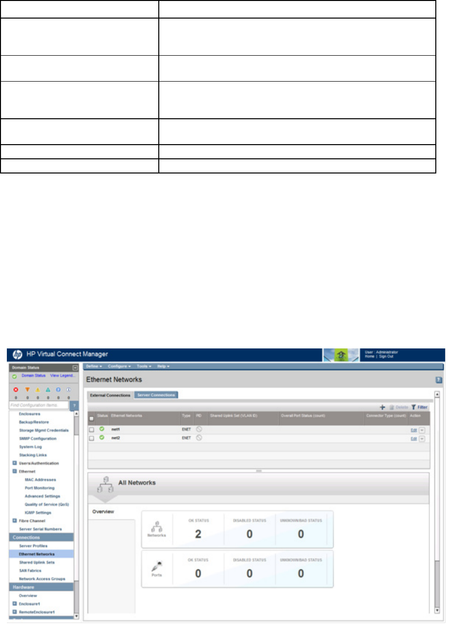
Ethernet Networks (External Connections) screen
To access this screen, click the Ethernet Networks link in the left navigation tree, and then click the External
Connections tab.
This summary screen displays the external connections for each network and is available to all authorized
users.