
HP Virtual Connect for c-Class BladeSystem Version 4.01 User Guide
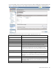
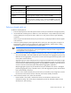

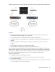
Table Of Contents
- HP Virtual Connect for c-Class BladeSystem Version 4.01 User Guide
- Abstract
- Notice
- Contents
- Introduction
- HP Virtual Connect Manager
- Virtual Connect domains
- Understanding Virtual Connect domains
- Managing domains
- Managing SNMP
- Viewing the system log
- Managing SSL configuration
- HP BladeSystem c-Class enclosures
- Virtual Connect users and roles
- Understanding VC administrative roles
- Managing users
- Local Users screen
- Configuring LDAP, RADIUS, and TACACS+
- Minimum requirements
- LDAP Server Settings (LDAP Server) screen
- LDAP Server Settings (LDAP Groups) screen
- LDAP Server Settings (LDAP Certificate) screen
- RADIUS Settings (RADIUS Server) screen
- RADIUS Settings (RADIUS Groups) screen
- TACACS+ Settings screen
- Role Management (Role Authentication Order) screen
- Role Management (Role Operations) screen
- Virtual Connect networks
- Understanding networks and shared uplink sets
- Managing networks
- Network Access Groups screen
- Define Network Access Group screen
- Ethernet Settings (Port Monitoring) screen
- Ethernet Settings (Advanced Settings) screen
- Quality of Service
- IGMP Settings (IGMP Configuration) screen
- IGMP Settings (Multicast Filter Set) screen
- Define Ethernet Network screen
- Ethernet Networks (External Connections) screen
- Ethernet Networks (Server Connections) screen
- Managing shared uplink sets
- Virtual Connect fabrics
- Virtual Connect server profiles
- Understanding server profiles
- Managing MAC, WWN, and server virtual ID settings
- Managing server profiles
- Define Server Profile screen
- Creating FCoE HBA connections for a BL890c i4
- Limited Ethernet connections when using HP Virtual Connect Flex-10/10D modules
- Creating iSCSI connections
- Flex-10 iSCSI connections
- Define Server Profile screen (multiple enclosures)
- Multiple network connections for a server port
- Defining server VLAN mappings
- Fibre Channel boot parameters
- Server Profiles screen
- Edit Server Profile screen
- Assigning a server profile with FCoE connections to an HP ProLiant BL680c G7 Server Blade
- Unassigning a server profile with FCoE connections to an HP ProLiant BL680c G7 Server Blade and deleting the SAN fabric
- General requirements for adding FC or FCoE connections
- Define Server Profile screen
- Virtual Connect and Insight Control Server Deployment
- Virtual Connect modules
- Firmware updates
- Stacking Links screen
- Throughput Statistics screen
- Enclosure Information screen
- Enclosure Status screen
- Interconnect Bays Status and Summary screen
- Causes for INCOMPATIBLE status
- Ethernet Bay Summary (General Information) screen
- Ethernet Bay Summary (Uplink Port Information) screen
- Ethernet Bay Summary (Server Port Information) screen
- Ethernet Bay Summary (MAC Address Table) screen
- Ethernet Bay Summary (IGMP Multicast Groups) screen
- Ethernet Bay Summary (Name Server) screen
- Ethernet Port Detailed Statistics screen
- FC Port Detailed Statistics screen
- FC Bay Summary screen
- Interconnect Bay Overall Status icon definitions
- Interconnect Bay OA Reported Status icon definitions
- Interconnect Bay VC Status icon definitions
- Interconnect Bay OA Communication Status icon definitions
- Server Bays Summary screen
- Server Bay Status screen
- Port status conditions
- Interconnect module removal and replacement
- Virtual Connect modules
- Upgrading to an HP Virtual Connect 8Gb 24-Port FC Module
- Upgrading to an HP Virtual Connect 8Gb 20-Port FC Module
- Upgrading or removing an HP Virtual Connect Flex-10, HP Virtual Connect FlexFabric, or HP Virtual Connect Flex-10/10D module
- Upgrading to an HP Virtual Connect FlexFabric module from a VC-FC module
- Onboard Administrator modules
- Maintenance and troubleshooting
- Appendix: Using Virtual Connect with nPartitions
- Support and other resources
- Acronyms and abbreviations
- Documentation feedback
- Index
Virtual Connect networks 129
Set preferred connection speed. This value is the default speed for server profile connections
mapped to this network. The server administrator can override this setting on an individual
profile connection.
Set maximum connection speed. This value is the maximum speed for server profile connections
mapped to this network. This speed limits the maximum port speed from the server to the network
connection associated with the multiple networks.
8. Click Apply. The shared uplink and associated networks are now defined and available for use in
creating server profiles.
Defining an FCoE network
You can create an FCoE network by creating a Shared Uplink Set and then adding an FCoE network to it.
You cannot create an FCoE network independently outside of a Shared Uplink Set.
Dual-hop FCoE support
Prior to the VC v4.01 release, VCM support of FCoE did not extend outside of the enclosure. All FCoE traffic
was converted to native FC prior to reaching VC interconnect uplinks. This solution required a FC switch to
be connected to the VC interconnects. The Dual-hop FCoE feature of VC allows FCoE traffic to be propagated
out of the enclosure to an external FCoE-capable bridge which will handle the conversion of FCoE to FC
traffic and vice-versa. This allows server connections to use Ethernet transport and results in the following
benefits:
• Cable consolidation
• Reduction in the number of per server adapters and interconnects required
• Reduction in utilization of the upstream switch ports
• Ease and simplification of management
This feature is called FCoE Dual Hop because there are two FCoE ‘hops’ between the server and the
conversion point from FCoE to FC. The first hop is between the server CNA adapter and the VC Module. The
second hop is between the VC Modules and the external FCoE à FC bridge device. No additional external
FCoE bridges or gateways can be in this configuration. Introducing an additional external FCoE bridge or
gateway would make it impossible to guarantee the lossless handling of the traffic and ensure
congestion-free connectivity.
This feature is supported on VC FlexFabric or VC Flex-10/10D modules. VC FlexFabric modules support
FCoE on uplink ports X1-X4 while the VC Flex10/10D modules support FCoE on all uplink ports (X1-X10).
FCoE traffic is forwarded to the top-of-rack (ToR) device which performs the FCoE to FC traffic conversion. The
ToR device must act as either a bridge to the native FC infrastructure or directly connect to FC-based Storage
devices.
The following FCoE capable ToR switches have been tested and are supported with this feature:
• HP 5820-14XG ToR 10GbE Switch with 5820 4-port 8/4/2 Gbps FCoE SFP Module operating in
FCoE Gateway mode
• Cisco Nexus 5xxx switches (50x0 and 55xx) operating as either NPV Gateway or FC Forwarder (FCF).
In FCF mode, FC SAN switches must be Cisco MDS family for interoperability.