
HP Virtual Connect for c-Class BladeSystem Version 4.01 User Guide
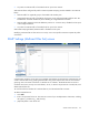
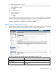
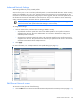
Table Of Contents
- HP Virtual Connect for c-Class BladeSystem Version 4.01 User Guide
- Abstract
- Notice
- Contents
- Introduction
- HP Virtual Connect Manager
- Virtual Connect domains
- Understanding Virtual Connect domains
- Managing domains
- Managing SNMP
- Viewing the system log
- Managing SSL configuration
- HP BladeSystem c-Class enclosures
- Virtual Connect users and roles
- Understanding VC administrative roles
- Managing users
- Local Users screen
- Configuring LDAP, RADIUS, and TACACS+
- Minimum requirements
- LDAP Server Settings (LDAP Server) screen
- LDAP Server Settings (LDAP Groups) screen
- LDAP Server Settings (LDAP Certificate) screen
- RADIUS Settings (RADIUS Server) screen
- RADIUS Settings (RADIUS Groups) screen
- TACACS+ Settings screen
- Role Management (Role Authentication Order) screen
- Role Management (Role Operations) screen
- Virtual Connect networks
- Understanding networks and shared uplink sets
- Managing networks
- Network Access Groups screen
- Define Network Access Group screen
- Ethernet Settings (Port Monitoring) screen
- Ethernet Settings (Advanced Settings) screen
- Quality of Service
- IGMP Settings (IGMP Configuration) screen
- IGMP Settings (Multicast Filter Set) screen
- Define Ethernet Network screen
- Ethernet Networks (External Connections) screen
- Ethernet Networks (Server Connections) screen
- Managing shared uplink sets
- Virtual Connect fabrics
- Virtual Connect server profiles
- Understanding server profiles
- Managing MAC, WWN, and server virtual ID settings
- Managing server profiles
- Define Server Profile screen
- Creating FCoE HBA connections for a BL890c i4
- Limited Ethernet connections when using HP Virtual Connect Flex-10/10D modules
- Creating iSCSI connections
- Flex-10 iSCSI connections
- Define Server Profile screen (multiple enclosures)
- Multiple network connections for a server port
- Defining server VLAN mappings
- Fibre Channel boot parameters
- Server Profiles screen
- Edit Server Profile screen
- Assigning a server profile with FCoE connections to an HP ProLiant BL680c G7 Server Blade
- Unassigning a server profile with FCoE connections to an HP ProLiant BL680c G7 Server Blade and deleting the SAN fabric
- General requirements for adding FC or FCoE connections
- Define Server Profile screen
- Virtual Connect and Insight Control Server Deployment
- Virtual Connect modules
- Firmware updates
- Stacking Links screen
- Throughput Statistics screen
- Enclosure Information screen
- Enclosure Status screen
- Interconnect Bays Status and Summary screen
- Causes for INCOMPATIBLE status
- Ethernet Bay Summary (General Information) screen
- Ethernet Bay Summary (Uplink Port Information) screen
- Ethernet Bay Summary (Server Port Information) screen
- Ethernet Bay Summary (MAC Address Table) screen
- Ethernet Bay Summary (IGMP Multicast Groups) screen
- Ethernet Bay Summary (Name Server) screen
- Ethernet Port Detailed Statistics screen
- FC Port Detailed Statistics screen
- FC Bay Summary screen
- Interconnect Bay Overall Status icon definitions
- Interconnect Bay OA Reported Status icon definitions
- Interconnect Bay VC Status icon definitions
- Interconnect Bay OA Communication Status icon definitions
- Server Bays Summary screen
- Server Bay Status screen
- Port status conditions
- Interconnect module removal and replacement
- Virtual Connect modules
- Upgrading to an HP Virtual Connect 8Gb 24-Port FC Module
- Upgrading to an HP Virtual Connect 8Gb 20-Port FC Module
- Upgrading or removing an HP Virtual Connect Flex-10, HP Virtual Connect FlexFabric, or HP Virtual Connect Flex-10/10D module
- Upgrading to an HP Virtual Connect FlexFabric module from a VC-FC module
- Onboard Administrator modules
- Maintenance and troubleshooting
- Appendix: Using Virtual Connect with nPartitions
- Support and other resources
- Acronyms and abbreviations
- Documentation feedback
- Index

Virtual Connect networks 117
9.
Select the speed and duplex (where applicable) of the uplink ports. Click the pull-down box under
Speed/Duplex, and then select a setting. Half-duplex operation is not supported by the VC-Enet
module.
IMPORTANT: Be sure that the uplink interface port speed matches the speed set on the
corresponding network switch port. If using autonegotiation, both ports must be configured to use
autonegotiation or they might not link.
10. Select the Connection Mode:
o Auto (recommended)—This mode enables the uplinks to attempt to form aggregation groups using
IEEE 802.3ad link aggregation control protocol, and to select the highest performing uplink as the
active path to external networks.
Aggregation groups require multiple ports from a single VC-Enet module to be connected to a single
external switch that supports automatic formation of LACP aggregation groups, or multiple external
switches that utilize distributed link aggregation. HP has guidelines available for users who prefer
to connect to external switches that support distributed link aggregation capabilities.
Multiple aggregation groups may be formed from the ports selected for the network. The highest
performing aggregation group is selected as active, with other aggregation groups and individual
links used as standby connections.
o Failover—If this mode is selected, set the port to Primary or Secondary. Only a single link is used as
the active link to the external networks, with other ports used as standby connections.
11. Select the LACP Timer, if the Connect Mode is Auto:
o Domain Default—If this mode is selected, the network uses the domain-wide LACP timer
configuration setting. The current setting is displayed as a part of the radio button label. See the
descriptions for Short and Long.
o Short—If this mode is selected, VC requests short (every 1 second) LACP control messages on a LAG
that is formed with the uplink ports.
o Long—If this mode is selected, VC requests long (every 30 seconds) LACP control messages on a
LAG that is formed with the uplink ports.
12. In the Network Access Groups field, begin typing the name of a Network Access Group that should
include this network. When the Network Access Group name appears, select the name.
To use a network access group, it must already be defined. For more information, see "Define Network
Access Group screen (on page 89)."
13. Click Apply. The network is now defined and available for use in creating server profiles.
To define a network that uses an existing Shared Uplink Set, either use the Define/Edit Shared Uplink Set
screen, or define the additional network as follows:
1. Enter the network name.
2. Select the Use Shared Uplink Set box.
3. Select an existing Shared Uplink Set from the pull-down list.
4. Enter an external VLAN ID.
5. Click Apply.
IMPORTANT:
For best performance, HP recommends limiting the number of shared uplinks sets
in one domain to two. There is a 1000 network limit per Virtual Connect domain.