
HP Virtual Connect for c-Class BladeSystem Version 4.01 User Guide
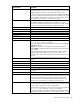
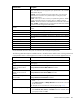
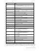
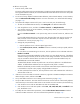
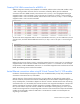
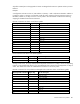
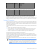
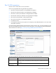
Table Of Contents
- HP Virtual Connect for c-Class BladeSystem Version 4.01 User Guide
- Abstract
- Notice
- Contents
- Introduction
- HP Virtual Connect Manager
- Virtual Connect domains
- Understanding Virtual Connect domains
- Managing domains
- Managing SNMP
- Viewing the system log
- Managing SSL configuration
- HP BladeSystem c-Class enclosures
- Virtual Connect users and roles
- Understanding VC administrative roles
- Managing users
- Local Users screen
- Configuring LDAP, RADIUS, and TACACS+
- Minimum requirements
- LDAP Server Settings (LDAP Server) screen
- LDAP Server Settings (LDAP Groups) screen
- LDAP Server Settings (LDAP Certificate) screen
- RADIUS Settings (RADIUS Server) screen
- RADIUS Settings (RADIUS Groups) screen
- TACACS+ Settings screen
- Role Management (Role Authentication Order) screen
- Role Management (Role Operations) screen
- Virtual Connect networks
- Understanding networks and shared uplink sets
- Managing networks
- Network Access Groups screen
- Define Network Access Group screen
- Ethernet Settings (Port Monitoring) screen
- Ethernet Settings (Advanced Settings) screen
- Quality of Service
- IGMP Settings (IGMP Configuration) screen
- IGMP Settings (Multicast Filter Set) screen
- Define Ethernet Network screen
- Ethernet Networks (External Connections) screen
- Ethernet Networks (Server Connections) screen
- Managing shared uplink sets
- Virtual Connect fabrics
- Virtual Connect server profiles
- Understanding server profiles
- Managing MAC, WWN, and server virtual ID settings
- Managing server profiles
- Define Server Profile screen
- Creating FCoE HBA connections for a BL890c i4
- Limited Ethernet connections when using HP Virtual Connect Flex-10/10D modules
- Creating iSCSI connections
- Flex-10 iSCSI connections
- Define Server Profile screen (multiple enclosures)
- Multiple network connections for a server port
- Defining server VLAN mappings
- Fibre Channel boot parameters
- Server Profiles screen
- Edit Server Profile screen
- Assigning a server profile with FCoE connections to an HP ProLiant BL680c G7 Server Blade
- Unassigning a server profile with FCoE connections to an HP ProLiant BL680c G7 Server Blade and deleting the SAN fabric
- General requirements for adding FC or FCoE connections
- Define Server Profile screen
- Virtual Connect and Insight Control Server Deployment
- Virtual Connect modules
- Firmware updates
- Stacking Links screen
- Throughput Statistics screen
- Enclosure Information screen
- Enclosure Status screen
- Interconnect Bays Status and Summary screen
- Causes for INCOMPATIBLE status
- Ethernet Bay Summary (General Information) screen
- Ethernet Bay Summary (Uplink Port Information) screen
- Ethernet Bay Summary (Server Port Information) screen
- Ethernet Bay Summary (MAC Address Table) screen
- Ethernet Bay Summary (IGMP Multicast Groups) screen
- Ethernet Bay Summary (Name Server) screen
- Ethernet Port Detailed Statistics screen
- FC Port Detailed Statistics screen
- FC Bay Summary screen
- Interconnect Bay Overall Status icon definitions
- Interconnect Bay OA Reported Status icon definitions
- Interconnect Bay VC Status icon definitions
- Interconnect Bay OA Communication Status icon definitions
- Server Bays Summary screen
- Server Bay Status screen
- Port status conditions
- Interconnect module removal and replacement
- Virtual Connect modules
- Upgrading to an HP Virtual Connect 8Gb 24-Port FC Module
- Upgrading to an HP Virtual Connect 8Gb 20-Port FC Module
- Upgrading or removing an HP Virtual Connect Flex-10, HP Virtual Connect FlexFabric, or HP Virtual Connect Flex-10/10D module
- Upgrading to an HP Virtual Connect FlexFabric module from a VC-FC module
- Onboard Administrator modules
- Maintenance and troubleshooting
- Appendix: Using Virtual Connect with nPartitions
- Support and other resources
- Acronyms and abbreviations
- Documentation feedback
- Index
Virtual Connect server profiles 185
After selecting an item from the pull-down menu in the SAN Boot Setting column, you must click outside
the grid to complete the selection. This is the same procedure that is followed when selecting a fabric or
network for an FC or Ethernet connection, respectively. After the Boot Setting column has been
completed, you can edit the Target Port Name and LUN.
8. Set up FCoE HBA connections:
o Click on the down arrow under FC SAN/FCoE Network Name to select an available SAN or FCoE
network.
o Click on the Port speed to select 1, 2, 4, 8, Custom, Preferred, or Disabled for SAN connections or
Auto, Custom, Preferred, or Disabled for FCoE connections. The default is Preferred, and the Custom
option allows you to choose a value between 100Mb and 10Gb in 100Mb intervals.
For an FCoE network, if Auto is selected for the port speed, VCM determines the appropriate port
speed based on the available bandwidth for the port.
9. To modify the Fibre Channel boot parameters for booting over FCoE, select the Fibre Channel Boot
Parameters checkbox under the FCoE HBA connections. See "Fibre Channel boot parameters (on page
199)."
After selecting an item from the pull-down menu in the SAN Boot Setting column, you must click outside
the grid to complete the selection. This is the same procedure that is followed when selecting a fabric or
network for an FC or Ethernet connection, respectively. After the Boot Setting column has been
completed, you can edit the Target Port Name and LUN.
10. To assign the server profile to a device bay, click the down arrow next to Select Location to select an
enclosure and bay number. This step can be deferred.
If the VC domain is configured for double-dense server mode, and a profile is assigned to an empty
server bay, then a hot-plug installation of a single-dense server into that server bay results in the profile
not being activated. To recover the profile, unassign the profile, and then reassign it.
Be sure that the type of server blade in the bay, or planned for the bay, can support the configuration.
For example, not all server blades support FCoE connections.
If a server blade is present in the selected location, it must be powered off for the profile to be saved and
assigned properly.
For more information on server power requirements when assigning or removing server profiles, see
"Server profile troubleshooting (on page 273)."
11. Click Apply to save current changes and remain on this screen. Click Apply & Close to apply the
changes and go to the Server Profiles summary screen.