
HP Virtual Connect for c-Class BladeSystem Version 4.01 User Guide
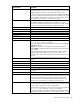
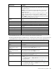
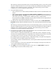
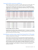
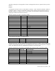
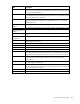
Table Of Contents
- HP Virtual Connect for c-Class BladeSystem Version 4.01 User Guide
- Abstract
- Notice
- Contents
- Introduction
- HP Virtual Connect Manager
- Virtual Connect domains
- Understanding Virtual Connect domains
- Managing domains
- Managing SNMP
- Viewing the system log
- Managing SSL configuration
- HP BladeSystem c-Class enclosures
- Virtual Connect users and roles
- Understanding VC administrative roles
- Managing users
- Local Users screen
- Configuring LDAP, RADIUS, and TACACS+
- Minimum requirements
- LDAP Server Settings (LDAP Server) screen
- LDAP Server Settings (LDAP Groups) screen
- LDAP Server Settings (LDAP Certificate) screen
- RADIUS Settings (RADIUS Server) screen
- RADIUS Settings (RADIUS Groups) screen
- TACACS+ Settings screen
- Role Management (Role Authentication Order) screen
- Role Management (Role Operations) screen
- Virtual Connect networks
- Understanding networks and shared uplink sets
- Managing networks
- Network Access Groups screen
- Define Network Access Group screen
- Ethernet Settings (Port Monitoring) screen
- Ethernet Settings (Advanced Settings) screen
- Quality of Service
- IGMP Settings (IGMP Configuration) screen
- IGMP Settings (Multicast Filter Set) screen
- Define Ethernet Network screen
- Ethernet Networks (External Connections) screen
- Ethernet Networks (Server Connections) screen
- Managing shared uplink sets
- Virtual Connect fabrics
- Virtual Connect server profiles
- Understanding server profiles
- Managing MAC, WWN, and server virtual ID settings
- Managing server profiles
- Define Server Profile screen
- Creating FCoE HBA connections for a BL890c i4
- Limited Ethernet connections when using HP Virtual Connect Flex-10/10D modules
- Creating iSCSI connections
- Flex-10 iSCSI connections
- Define Server Profile screen (multiple enclosures)
- Multiple network connections for a server port
- Defining server VLAN mappings
- Fibre Channel boot parameters
- Server Profiles screen
- Edit Server Profile screen
- Assigning a server profile with FCoE connections to an HP ProLiant BL680c G7 Server Blade
- Unassigning a server profile with FCoE connections to an HP ProLiant BL680c G7 Server Blade and deleting the SAN fabric
- General requirements for adding FC or FCoE connections
- Define Server Profile screen
- Virtual Connect and Insight Control Server Deployment
- Virtual Connect modules
- Firmware updates
- Stacking Links screen
- Throughput Statistics screen
- Enclosure Information screen
- Enclosure Status screen
- Interconnect Bays Status and Summary screen
- Causes for INCOMPATIBLE status
- Ethernet Bay Summary (General Information) screen
- Ethernet Bay Summary (Uplink Port Information) screen
- Ethernet Bay Summary (Server Port Information) screen
- Ethernet Bay Summary (MAC Address Table) screen
- Ethernet Bay Summary (IGMP Multicast Groups) screen
- Ethernet Bay Summary (Name Server) screen
- Ethernet Port Detailed Statistics screen
- FC Port Detailed Statistics screen
- FC Bay Summary screen
- Interconnect Bay Overall Status icon definitions
- Interconnect Bay OA Reported Status icon definitions
- Interconnect Bay VC Status icon definitions
- Interconnect Bay OA Communication Status icon definitions
- Server Bays Summary screen
- Server Bay Status screen
- Port status conditions
- Interconnect module removal and replacement
- Virtual Connect modules
- Upgrading to an HP Virtual Connect 8Gb 24-Port FC Module
- Upgrading to an HP Virtual Connect 8Gb 20-Port FC Module
- Upgrading or removing an HP Virtual Connect Flex-10, HP Virtual Connect FlexFabric, or HP Virtual Connect Flex-10/10D module
- Upgrading to an HP Virtual Connect FlexFabric module from a VC-FC module
- Onboard Administrator modules
- Maintenance and troubleshooting
- Appendix: Using Virtual Connect with nPartitions
- Support and other resources
- Acronyms and abbreviations
- Documentation feedback
- Index
Virtual Connect server profiles 186
Creating FCoE HBA connections for a BL890c i4
Additional steps are necessary when a BL890c i4 is installed, and the enclosure has FCoE modules in bays
1 and 2. The figure below shows the first four connections created by default, plus four additional
connections that were added manually. The FCoE entries for I/O bays 1 and 2 (highlighted below) get
mapped to LOMs 1 and 2 on blades 1 and 2. The next pair of entries for I/O bays 1 and 2 would get
mapped to LOMs 1 and 2 on the third blade, and the fourth set of entries for I/O bays 1 and 2 would get
mapped to LOMs 1 and 2 on the fourth blade.
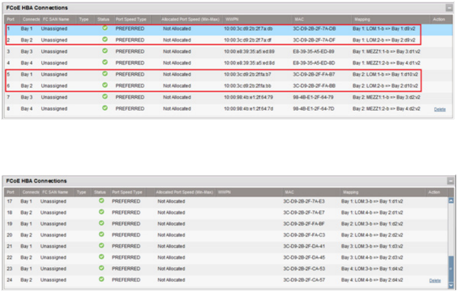
To have FCoE entries mapped to LOMs 3 and 4 on each blade in the server, you must add three extra sets
of FCoE entries, and then add the additional entries for I/O bays 1 and 2. See ports 17-24 in the figure
below.
Creating FCoE HBA connections for a BL870c i4
Referencing the previous figures, entries 1-8 would be mapped as shown. Entries 9 and 10 would then be
mapped to LOMs 3 and 4 on the first blade in the BL870c i4, entries 11-12 would be as in this example
except that they would be UNMAPPED, and entries 13-14 would be mapped to LOMs 3 and 4 on the second
blade. The remaining entries would not be needed.
Limited Ethernet connections when using HP Virtual Connect Flex-10/10D modules
Introduction of the dual-hop FCoE support in VCM v4.01 enabled the ability to map newly created FCoE
connections to the HP VC Flex-10/10D module.
With the extension of the support for FCoE to Flex-10/10D modules, the algorithm for mapping of the
Ethernet and FCoE connections to the FlexNIC and FlexHBA ports on the FlexFabric adapters changed. In the
newly created profiles, if a FlexFabric adapter was found in a LOM or Flexible LOM location while being
connected to a Flex-10/10D module, the first FCoE connection was assigned to that adapter. In the previous
releases only Ethernet connections could be assigned to a FlexFabric adapter that was connected to a
Flex-10/10D module. Only FCoE network created on a Shared Uplink Set originating on a Flex-10/10D
module can be assigned to the corresponding FCoE connection. FCoE connections that map to the FlexFabric
modules can be assigned to either FC SAN Fabric or FCoE Network created on a Shared Uplink Set
originating on this module.