
HP Virtual Connect 1Gb Ethernet Cookbook
Scenario 5 – VLAN Tagging (802.1Q) with a Shared Uplink Set (SUS) with Link Aggregation using LACP (802.3ad) –
VMware ESX 57
Scenario 5 – VLAN Tagging (802.1Q) with a
Shared Uplink Set (SUS) with Link
Aggregation using LACP (802.3ad) –
VMware ESX
Overview
This configuration uses single Virtual Connect Shared Uplink Set (SUS). The SUS provides the
ability to present a single or multiple VLANs to a server NIC. In this scenario, the upstream
network switch connects multiple VLANs to two ports on each VC module.
The single SUS is a popular configuration when supporting primarily East/West traffic patterns.
No matter which NIC a server is active on, if talking to another server within the enclosure on the
same VLAN, the traffic will remain within the VC/enclosure.
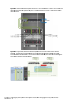
Requirements
In order to implement this scenario, an HP BladeSystem c7000 enclosure with one of more server
blades and TWO Virtual Connect Ethernet modules, installed in Bays 1& 2 are required. In
addition, we will require ONE or TWO external Network switches. As Virtual Connect does not
appear to the network as a switch and is transparent to the network, any standard managed
switch will work with Virtual Connect.
Configuring Uplinks to a vNet (LACP)
When all uplinks configured within a SUS connect a VC module to an upstream switch, ALL links
could be active, providing additional bandwidth, using Link Aggregation Protocol (LACP 802.3ad),
this requires the upstream switch to be configured, on these ports, for link aggregation control
protocol (LACP).
When some of the uplinks configured within a SUS connect a VC module to different upstream
switches, some links will be active and the remaining will be Standby, providing additional
bandwidth and/or availability, using Link Aggregation Protocol (LACP 802.3.ad). This scenario
will have both Active and Standby links.