
HP Virtual Connect for c-Class BladeSystem Setup and Install Guide Version 3.70 and 3.75

Installation 24
NOTE: The CX4 interface uses the same physical connector as Infiniband, but Infiniband cables
are tuned differently and will not perform as well in CX4 applications. HP recommends
purchasing CX4 cable assemblies that meet the IEEE CX4 specifications and support 10-Gigabit
communication at distances from 3 m to 15 m (9.84 ft to 49.20 ft).
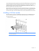
FlexFabric modules support DAC cables. For more information, see the VC FlexFabric module QuickSpecs
on the Installing tab of the HP BladeSystem Technical Resources website
(http://www.hp.com/go/bladesystem/documentation).
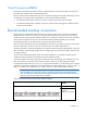
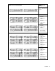
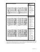
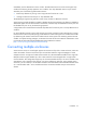
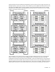
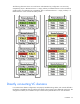
HP recommends fully redundant interconnection of VC-Enet modules. The recommended stacking
configurations have redundant connections. If a stacking cable is disconnected or fails, the Ethernet packets
within the Virtual Connect domain are automatically re-routed to the uplink through the redundant path. This
configuration also helps preserve network connectivity if an Ethernet interconnect module fails or is removed.
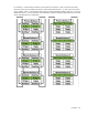
Network loop protection
To avoid network loops, Virtual Connect first verifies that only one active uplink exists per network from the
Virtual Connect domain to the external Ethernet switching environment. Second, Virtual Connect makes sure
that no network loops are created by the stacking links between Virtual Connect modules.
• One active link—A VC uplink set can include multiple uplink ports. To prevent a loop with broadcast
traffic coming in one uplink and going out another, only one uplink or uplink LAG is active at a time. The
uplink or LAG with the greatest bandwidth should be selected as the active uplink. If the active uplink
loses the link, then the next best uplink is made active.
• No loops through stacking links—If multiple VC-Enet modules are used, they are interconnected using
stacking links, which might appear as an opportunity for loops within the VC environment. For each
individual network in the Virtual Connect environment, VC blocks certain stacking links to ensure that
each network has a loop-free topology.
Enhanced network loop protection detects loops on downlink ports, which can be a Flex-10 logical port or
physical port. The feature applies to Flex-10 logical function if the Flex-10 port is operating under the control
of DCC protocol. If DCC is not available, the feature applies to a physical downlink port.
Enhanced network loop protection uses two methods to detect loops:
• It periodically injects a special probe frame into the VC domain and monitors downlink ports for the
looped back probe frame. If this special probe frame is detected on downlink ports, the port is
considered to cause the loop condition.
• It monitors and intercepts common loop detection frames used in other switches. In network
environments where the upstream switches send loop detection frames, the VC Enet modules must
ensure that any downlink loops do not cause these frames to be sent back to the uplink ports. Even
though VC probe frames ensure loops are detected, there is a small time window depending on the
probe frame transmission interval in which the loop detection frames from the external switch might loop
through down link ports and reach uplink ports. By intercepting the external loop detection frames on
downlinks, the possibility of triggering loop protection on the upstream switch is eliminated. When
network loop protection is enabled, VC-Enet modules intercept the following types of loop detection
frames:
o PVST+ BPDUs
o Procurve Loop Protect frames
When the network loop protection feature is enabled, any probe frame or other supported loop detection
frame received on a downlink port is considered to be causing the network loop, and the port is disabled