
HP Virtual Connect for c-Class BladeSystem User Guide


Installation 33
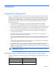
[Bay 7] Empty [Bay 8] Empty
[Bay 1] VC Ethernet [Bay 2] VC Ethernet
[Bay 3] VC-FC [Bay 4] VC-FC
[Bay 5] VC Ethernet [Bay 6] VC Ethernet
[Bay 7] VC Ethernet [Bay 8] VC Ethernet
[Bay 1] VC Ethernet [Bay 2] VC Ethernet
[Bay 3] Other/empty [Bay 4] Other/empty
[Bay 5] VC-FC [Bay 6] VC-FC
[Bay 7] Empty [Bay 8] Empty
[Bay 1] VC Ethernet [Bay 2] VC Ethernet
[Bay 3] VC-FC [Bay 4] VC-FC
[Bay 5] VC-FC [Bay 6] VC-FC
[Bay 7] Empty [Bay 8] Empty
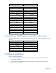
[Bay 1] VC Ethernet [Bay 2] VC Ethernet
[Bay 3] VC Ethernet [Bay 4] VC Ethernet
[Bay 5] VC Ethernet [Bay 6] VC Ethernet
[Bay 7] VC Ethernet [Bay 8] VC Ethernet
HP BladeSystem c3000 Enclosure supported configurations
The following tables show a number of typical, supported configurations for an HP BladeSystem c3000
Enclosure.
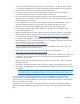
[Bay 1] VC Ethernet [Bay 2] VC Ethernet
[Bay 3] Empty [Bay 4] Empty
[Bay 1] VC Ethernet [Bay 2] VC Ethernet
[Bay 3] VC Ethernet [Bay 4] VC Ethernet
[Bay 1] VC Ethernet [Bay 2] VC Ethernet
[Bay 3] VC-FC [Bay 4] VC-FC
Installation guidelines
Observe the following guidelines:
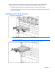
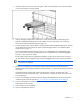
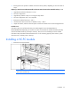
• To set up and configure Virtual Connect, interconnect bay 1 must be populated with a Virtual
Connect Ethernet module.
• To support failover configuration for Virtual Connect, install a second Virtual Connect Ethernet
module in interconnect bay 2.