
HP Virtual Connect for c-Class BladeSystem Version 3.00 Setup and Installation Guide for HP Integrity BL8x0c i2 Series Server Blades
Installation 57
Factory default settings
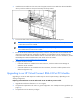
The Virtual Connect Delete Domain operation returns all VC-FC modules to the factory default settings.
VC-FC modules that are physically removed from a VC domain can be returned to the factory default
settings when placed into a new enclosure by applying power, and then pressing and holding the reset
button on the front panel for at least 10 seconds. When moved from a VC domain and placed into an
enclosure not part of a VC domain, VC-FC modules retain assigned mappings until reset to the factory
default.
Loop prevention
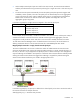
When link is established on a Virtual Connect Ethernet module port, the port exchanges LLDP packets with
the far-side connection. This LLDP protocol is an IEEE 802.1 standard that makes use of special BPDU
packets that are not forwarded by Ethernet bridges or switches. As part of the LLDP exchange, Virtual
Connect can determine whether a Virtual Connect Ethernet module port is connected to another port
within the same Virtual Connect domain. If the port is connected, the port is designated as a stacking link
and treated as such. If the port is not connected, then the port is available for use as an uplink port.
Only ports that have not been designated as an uplink port in a network are eligible to become stacking
links. If a port has been designated as an uplink port, and then is subsequently connected to another
Virtual Connect Ethernet module, the port will not become a stacking link until it is removed from the
network definition as an uplink port.
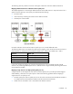
To avoid network loops, Virtual Connect must first verify that only one active uplink exists per network
from the Virtual Connect domain to the external Ethernet switching environment. Second, Virtual Connect
must be sure that no network loops are created by the stacking links between Virtual Connect modules.
• One active link—A VC uplink set can include multiple uplink ports. To prevent a loop with broadcast
traffic coming in one uplink and going out another, only one uplink or uplink LAG is active at a time.
The uplink or LAG with the greatest bandwidth should be selected as the active uplink. If the active
uplink loses link, then the next best uplink will be made active.
• No loops through stacking links—If multiple Virtual Connect Ethernet modules are used, they are
interconnected via stacking links, which might appear as an opportunity for loops within the VC
environment. For each individual network in the Virtual Connect environment, VC will block certain
stacking links to ensure that each network has a loop-free topology.
The loop avoidance feature can not be disabled or changed. However, the preferred uplink connection
for a network can be identified when defining network uplinks.
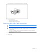
Connecting Virtual Connect Ethernet module uplinks
Each interconnect module has several numbered Ethernet connectors. All of these connectors can be used
to connect to data center switches (uplink ports), or they can be used to stack Virtual Connect modules as
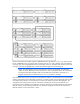
part of a single Virtual Connect domain (stacking ports). See "Recommended stacking connections (on
page 55)."
Networks must be defined within the Virtual Connect Manager so that specific, named networks can be
associated with specific external data center connections. These named networks can then be used to
specify networking connectivity for individual servers. For more information on defining Ethernet networks
and on server connections, see the HP Virtual Connect for c-Class BladeSystem User Guide.