
HP Virtual Connect for c-Class BladeSystem Version 4.01 User Guide
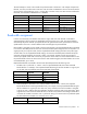
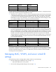
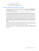
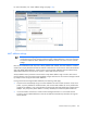
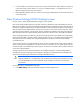
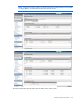
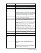
Table Of Contents
- HP Virtual Connect for c-Class BladeSystem Version 4.01 User Guide
- Abstract
- Notice
- Contents
- Introduction
- HP Virtual Connect Manager
- Virtual Connect domains
- Understanding Virtual Connect domains
- Managing domains
- Managing SNMP
- Viewing the system log
- Managing SSL configuration
- HP BladeSystem c-Class enclosures
- Virtual Connect users and roles
- Understanding VC administrative roles
- Managing users
- Local Users screen
- Configuring LDAP, RADIUS, and TACACS+
- Minimum requirements
- LDAP Server Settings (LDAP Server) screen
- LDAP Server Settings (LDAP Groups) screen
- LDAP Server Settings (LDAP Certificate) screen
- RADIUS Settings (RADIUS Server) screen
- RADIUS Settings (RADIUS Groups) screen
- TACACS+ Settings screen
- Role Management (Role Authentication Order) screen
- Role Management (Role Operations) screen
- Virtual Connect networks
- Understanding networks and shared uplink sets
- Managing networks
- Network Access Groups screen
- Define Network Access Group screen
- Ethernet Settings (Port Monitoring) screen
- Ethernet Settings (Advanced Settings) screen
- Quality of Service
- IGMP Settings (IGMP Configuration) screen
- IGMP Settings (Multicast Filter Set) screen
- Define Ethernet Network screen
- Ethernet Networks (External Connections) screen
- Ethernet Networks (Server Connections) screen
- Managing shared uplink sets
- Virtual Connect fabrics
- Virtual Connect server profiles
- Understanding server profiles
- Managing MAC, WWN, and server virtual ID settings
- Managing server profiles
- Define Server Profile screen
- Creating FCoE HBA connections for a BL890c i4
- Limited Ethernet connections when using HP Virtual Connect Flex-10/10D modules
- Creating iSCSI connections
- Flex-10 iSCSI connections
- Define Server Profile screen (multiple enclosures)
- Multiple network connections for a server port
- Defining server VLAN mappings
- Fibre Channel boot parameters
- Server Profiles screen
- Edit Server Profile screen
- Assigning a server profile with FCoE connections to an HP ProLiant BL680c G7 Server Blade
- Unassigning a server profile with FCoE connections to an HP ProLiant BL680c G7 Server Blade and deleting the SAN fabric
- General requirements for adding FC or FCoE connections
- Define Server Profile screen
- Virtual Connect and Insight Control Server Deployment
- Virtual Connect modules
- Firmware updates
- Stacking Links screen
- Throughput Statistics screen
- Enclosure Information screen
- Enclosure Status screen
- Interconnect Bays Status and Summary screen
- Causes for INCOMPATIBLE status
- Ethernet Bay Summary (General Information) screen
- Ethernet Bay Summary (Uplink Port Information) screen
- Ethernet Bay Summary (Server Port Information) screen
- Ethernet Bay Summary (MAC Address Table) screen
- Ethernet Bay Summary (IGMP Multicast Groups) screen
- Ethernet Bay Summary (Name Server) screen
- Ethernet Port Detailed Statistics screen
- FC Port Detailed Statistics screen
- FC Bay Summary screen
- Interconnect Bay Overall Status icon definitions
- Interconnect Bay OA Reported Status icon definitions
- Interconnect Bay VC Status icon definitions
- Interconnect Bay OA Communication Status icon definitions
- Server Bays Summary screen
- Server Bay Status screen
- Port status conditions
- Interconnect module removal and replacement
- Virtual Connect modules
- Upgrading to an HP Virtual Connect 8Gb 24-Port FC Module
- Upgrading to an HP Virtual Connect 8Gb 20-Port FC Module
- Upgrading or removing an HP Virtual Connect Flex-10, HP Virtual Connect FlexFabric, or HP Virtual Connect Flex-10/10D module
- Upgrading to an HP Virtual Connect FlexFabric module from a VC-FC module
- Onboard Administrator modules
- Maintenance and troubleshooting
- Appendix: Using Virtual Connect with nPartitions
- Support and other resources
- Acronyms and abbreviations
- Documentation feedback
- Index

Virtual Connect server profiles 172
Requested Allocated
FlexNIC b
Auto 3Gb
FlexNIC c
Auto 3Gb
FlexNIC d
Auto 3Gb
In cases where the requested bandwidth settings you specified for the four FlexNICs in a single physical port
exceed 10Gb, the following rules are applied in this order:
1. If FlexNICs with a "preferred" or "custom" value for requested bandwidth exceed 10Gb, each FlexNIC
is allocated bandwidth proportional to its requested bandwidth setting. For example, if four FlexNICs
on a given port have requested bandwidth settings of 1Gb, 2Gb, 4Gb, and 5Gb, their allocated
bandwidth is as shown in the table below. In this example, 200Mb remains after dividing the 10Gb
link. 100Mb is added to the two connections with the least bandwidth.
Requested Calculation Allocation + remainder
FlexNIC a
1Gb (1/12)*10Gb = 800Mb 900Mb
FlexNIC b
2Gb (2/12)*10Gb = 1600Mb 1700Mb
FlexNIC c
4Gb (4/12)*10Gb = 3300Mb 3300Mb
FlexNIC d
5Gb (5/12)*10Gb = 4100Mb 4100Mb
2. Every FlexNIC that is linked must be allocated at least 100Mb. For example, if four FlexNICs on a given
port have requested bandwidth settings of 2Gb, 8Gb, Auto, and Auto, their allocated bandwidth is as
shown in the table below. In this example, 100Mb must be allocated to the two FlexNICs set to "Auto"
because no bandwidth would remain after allocating 2Gb and 8Gb to the first two FlexNICs. The two
FlexNICs set for 2Gb and 8Gb requested bandwidth are allocated a proportion of the 9800Mb
remaining after the two FlexNICs set to "Auto" receive 100Mb. In this example, there is a remainder of
100Mb, and that remainder is assigned to the FlexNIC whose allocated bandwidth differs the most
from its requested bandwidth.
Requested Calculation Allocation + remainder
FlexNIC a
2Gb (2/10)*9800Mb = 1900Mb 2000Mb
FlexNIC b
8Gb (8/10)*9800Mb = 7800Mb 7800Mb
FlexNIC c
Auto
100Mb
100Mb
FlexNIC d
Auto 100Mb 100Mb
For FlexFabric configurations, the allocated bandwidth for the assigned FCoE connections takes precedence
over the Enet connections in all cases. This implies that if you add FCoE connection bandwidth to a server
port that has both Enet and FCoE connections on different PFs, the Enet connection has less bandwidth
according to the rules stated above.
Managing MAC, WWN, and server virtual ID
settings
Use the following screens to manage MAC, WWN, and server virtual ID settings:
• Ethernet Settings (MAC Addresses) screen (on page 173)
o Select MAC addresses for server profiles
• Fibre Channel Settings (WWN Settings) screen (on page 175)