
HP Virtual Connect for c-Class BladeSystem Version 4.01 User Guide
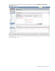
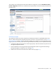
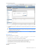
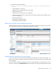
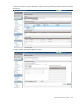
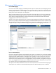
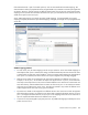
Table Of Contents
- HP Virtual Connect for c-Class BladeSystem Version 4.01 User Guide
- Abstract
- Notice
- Contents
- Introduction
- HP Virtual Connect Manager
- Virtual Connect domains
- Understanding Virtual Connect domains
- Managing domains
- Managing SNMP
- Viewing the system log
- Managing SSL configuration
- HP BladeSystem c-Class enclosures
- Virtual Connect users and roles
- Understanding VC administrative roles
- Managing users
- Local Users screen
- Configuring LDAP, RADIUS, and TACACS+
- Minimum requirements
- LDAP Server Settings (LDAP Server) screen
- LDAP Server Settings (LDAP Groups) screen
- LDAP Server Settings (LDAP Certificate) screen
- RADIUS Settings (RADIUS Server) screen
- RADIUS Settings (RADIUS Groups) screen
- TACACS+ Settings screen
- Role Management (Role Authentication Order) screen
- Role Management (Role Operations) screen
- Virtual Connect networks
- Understanding networks and shared uplink sets
- Managing networks
- Network Access Groups screen
- Define Network Access Group screen
- Ethernet Settings (Port Monitoring) screen
- Ethernet Settings (Advanced Settings) screen
- Quality of Service
- IGMP Settings (IGMP Configuration) screen
- IGMP Settings (Multicast Filter Set) screen
- Define Ethernet Network screen
- Ethernet Networks (External Connections) screen
- Ethernet Networks (Server Connections) screen
- Managing shared uplink sets
- Virtual Connect fabrics
- Virtual Connect server profiles
- Understanding server profiles
- Managing MAC, WWN, and server virtual ID settings
- Managing server profiles
- Define Server Profile screen
- Creating FCoE HBA connections for a BL890c i4
- Limited Ethernet connections when using HP Virtual Connect Flex-10/10D modules
- Creating iSCSI connections
- Flex-10 iSCSI connections
- Define Server Profile screen (multiple enclosures)
- Multiple network connections for a server port
- Defining server VLAN mappings
- Fibre Channel boot parameters
- Server Profiles screen
- Edit Server Profile screen
- Assigning a server profile with FCoE connections to an HP ProLiant BL680c G7 Server Blade
- Unassigning a server profile with FCoE connections to an HP ProLiant BL680c G7 Server Blade and deleting the SAN fabric
- General requirements for adding FC or FCoE connections
- Define Server Profile screen
- Virtual Connect and Insight Control Server Deployment
- Virtual Connect modules
- Firmware updates
- Stacking Links screen
- Throughput Statistics screen
- Enclosure Information screen
- Enclosure Status screen
- Interconnect Bays Status and Summary screen
- Causes for INCOMPATIBLE status
- Ethernet Bay Summary (General Information) screen
- Ethernet Bay Summary (Uplink Port Information) screen
- Ethernet Bay Summary (Server Port Information) screen
- Ethernet Bay Summary (MAC Address Table) screen
- Ethernet Bay Summary (IGMP Multicast Groups) screen
- Ethernet Bay Summary (Name Server) screen
- Ethernet Port Detailed Statistics screen
- FC Port Detailed Statistics screen
- FC Bay Summary screen
- Interconnect Bay Overall Status icon definitions
- Interconnect Bay OA Reported Status icon definitions
- Interconnect Bay VC Status icon definitions
- Interconnect Bay OA Communication Status icon definitions
- Server Bays Summary screen
- Server Bay Status screen
- Port status conditions
- Interconnect module removal and replacement
- Virtual Connect modules
- Upgrading to an HP Virtual Connect 8Gb 24-Port FC Module
- Upgrading to an HP Virtual Connect 8Gb 20-Port FC Module
- Upgrading or removing an HP Virtual Connect Flex-10, HP Virtual Connect FlexFabric, or HP Virtual Connect Flex-10/10D module
- Upgrading to an HP Virtual Connect FlexFabric module from a VC-FC module
- Onboard Administrator modules
- Maintenance and troubleshooting
- Appendix: Using Virtual Connect with nPartitions
- Support and other resources
- Acronyms and abbreviations
- Documentation feedback
- Index
Virtual Connect server profiles 197
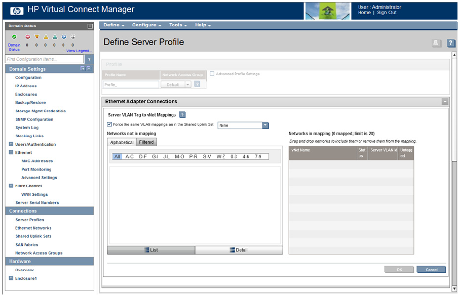
Defining server VLAN mappings
Forced VLAN Mappings
If the 'Force same VLAN mappings as Shared Uplink Sets' option is selected, server VLAN mappings are the
same as the shared uplink set VLAN mappings. You can choose only from a list of shared uplink sets when
selecting Multiple Networks. After selecting a shared uplink set from the pull-down list, a list of VLANs that
belong to the chosen shared uplink set is displayed.
The server VLAN mappings are the same as those used on the shared uplink set, which are automatically
displayed and cannot be changed. One of the networks can also be selected as the 'Untagged' network,
which means that untagged packets are placed on that VLAN, and the VC-Enet module also transmits
untagged packets to the server for that network.
With this 'forced' option selected, the server connection VLAN mappings are linked to the chosen shared
uplink set. Any change to the uplink VLAN mappings is reflected automatically on the server connection using
those shared uplink set VLAN mappings. Therefore, to minimize network outage time, any VLAN mapping
changes to the uplinks requires immediate changes being made to the VLAN tagging on the servers.
No Forced VLAN Mappings
If the 'Force same VLAN mappings as Shared Uplink Sets' option is not selected, you can choose available
networks and assign a unique server VLAN associated with the network for this server port. Not forcing VLAN
mappings provides greater flexibility in selecting the set of networks to connect to each server port, and
enables administrators to specify server VLAN mappings independent of those assigned by the network
administrator for the shared uplink sets. The untagged option is always available, but it might be unassigned,
that is, any untagged frame from the server is dropped. Each network can be selected only once per server
port. Similarly, each server-assigned VLAN must be unique per server port.
This option is not available if the domain-wide 'Force server connections to use the same VLAN mappings as
shared uplink sets' checkbox on the Advanced Settings tab of the Ethernet Settings screen is selected.