
HP Virtual Connect for c-Class BladeSystem Version 4.01 User Guide
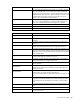
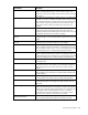
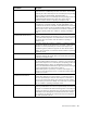
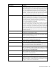
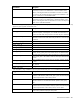
Table Of Contents
- HP Virtual Connect for c-Class BladeSystem Version 4.01 User Guide
- Abstract
- Notice
- Contents
- Introduction
- HP Virtual Connect Manager
- Virtual Connect domains
- Understanding Virtual Connect domains
- Managing domains
- Managing SNMP
- Viewing the system log
- Managing SSL configuration
- HP BladeSystem c-Class enclosures
- Virtual Connect users and roles
- Understanding VC administrative roles
- Managing users
- Local Users screen
- Configuring LDAP, RADIUS, and TACACS+
- Minimum requirements
- LDAP Server Settings (LDAP Server) screen
- LDAP Server Settings (LDAP Groups) screen
- LDAP Server Settings (LDAP Certificate) screen
- RADIUS Settings (RADIUS Server) screen
- RADIUS Settings (RADIUS Groups) screen
- TACACS+ Settings screen
- Role Management (Role Authentication Order) screen
- Role Management (Role Operations) screen
- Virtual Connect networks
- Understanding networks and shared uplink sets
- Managing networks
- Network Access Groups screen
- Define Network Access Group screen
- Ethernet Settings (Port Monitoring) screen
- Ethernet Settings (Advanced Settings) screen
- Quality of Service
- IGMP Settings (IGMP Configuration) screen
- IGMP Settings (Multicast Filter Set) screen
- Define Ethernet Network screen
- Ethernet Networks (External Connections) screen
- Ethernet Networks (Server Connections) screen
- Managing shared uplink sets
- Virtual Connect fabrics
- Virtual Connect server profiles
- Understanding server profiles
- Managing MAC, WWN, and server virtual ID settings
- Managing server profiles
- Define Server Profile screen
- Creating FCoE HBA connections for a BL890c i4
- Limited Ethernet connections when using HP Virtual Connect Flex-10/10D modules
- Creating iSCSI connections
- Flex-10 iSCSI connections
- Define Server Profile screen (multiple enclosures)
- Multiple network connections for a server port
- Defining server VLAN mappings
- Fibre Channel boot parameters
- Server Profiles screen
- Edit Server Profile screen
- Assigning a server profile with FCoE connections to an HP ProLiant BL680c G7 Server Blade
- Unassigning a server profile with FCoE connections to an HP ProLiant BL680c G7 Server Blade and deleting the SAN fabric
- General requirements for adding FC or FCoE connections
- Define Server Profile screen
- Virtual Connect and Insight Control Server Deployment
- Virtual Connect modules
- Firmware updates
- Stacking Links screen
- Throughput Statistics screen
- Enclosure Information screen
- Enclosure Status screen
- Interconnect Bays Status and Summary screen
- Causes for INCOMPATIBLE status
- Ethernet Bay Summary (General Information) screen
- Ethernet Bay Summary (Uplink Port Information) screen
- Ethernet Bay Summary (Server Port Information) screen
- Ethernet Bay Summary (MAC Address Table) screen
- Ethernet Bay Summary (IGMP Multicast Groups) screen
- Ethernet Bay Summary (Name Server) screen
- Ethernet Port Detailed Statistics screen
- FC Port Detailed Statistics screen
- FC Bay Summary screen
- Interconnect Bay Overall Status icon definitions
- Interconnect Bay OA Reported Status icon definitions
- Interconnect Bay VC Status icon definitions
- Interconnect Bay OA Communication Status icon definitions
- Server Bays Summary screen
- Server Bay Status screen
- Port status conditions
- Interconnect module removal and replacement
- Virtual Connect modules
- Upgrading to an HP Virtual Connect 8Gb 24-Port FC Module
- Upgrading to an HP Virtual Connect 8Gb 20-Port FC Module
- Upgrading or removing an HP Virtual Connect Flex-10, HP Virtual Connect FlexFabric, or HP Virtual Connect Flex-10/10D module
- Upgrading to an HP Virtual Connect FlexFabric module from a VC-FC module
- Onboard Administrator modules
- Maintenance and troubleshooting
- Appendix: Using Virtual Connect with nPartitions
- Support and other resources
- Acronyms and abbreviations
- Documentation feedback
- Index

Virtual Connect modules 244
Port Statistic Description
EtherStatsCollisions
The best estimate of the total number of collisions on this Ethernet segment.
The value returned depends on the location of the RMON probe. Section
8.2.1.3 (10BASE-5) and section 10.3.1.3 (10BASE-2) of IEEE standard
802.3 states that a station must detect a collision, in the receive mode, if
three or more stations are transmitting simultaneously. A repeater port
must detect a collision when two or more stations are transmitting
simultaneously. Therefore, a probe placed on a repeater port could
record more collisions than a probe connected to a station on the same
segment would. Probe location plays a much smaller role when
considering 10BASE-T.
14.2.1.4 (10BASE-T) of IEEE standard 802.3 defines a collision as the
simultaneous presence of signals on the DO and RD circuits (transmitting
and receiving at the same time). A 10BASE-T station can only detect
collisions when it is transmitting. Therefore, probes placed on a station
and a repeater should report the same number of collisions. Additionally,
an RMON probe inside a repeater should ideally report collisions
between the repeater and one or more other hosts (transmit collisions as
defined by IEEE 802.3k) plus receiver collisions observed on any coax
segments to which the repeater is connected.
EtherStatsCRCAlignErrors
The total number of packets received that had a length (excluding framing
bits, but including FCS octets) of between 64 and 1518 octets, inclusive,
but had either a bad FCS with an integral number of octets (FCS Error) or
a bad FCS with a non-integral number of octets (Alignment Error)
TXNoErrors
All packets transmitted without errors, less oversized packets
RXNoErrors
All packets received without errors, less oversized and undersized
packets
Dot3StatsAlignmentErrors
A count of frames received on a particular interface that are not an
integral number of octets in length and do not pass the FCS check. The
count represented by an instance of this object is incremented when the
alignmentError status is returned by the MAC service to the LLC (or other
MAC user). According to the conventions of IEEE 802.3 Layer
Management, received frames for which multiple error conditions are
obtained are counted exclusively according to the error status presented
to the LLC. This counter does not increment for 8-bit wide group encoding
schemes.
Dot3StatsFCSErrors
A count of frames received on a particular interface that are an integral
number of octets in length but do not pass the FCS check. This count does
not include frames received with a frame-too-long or frame-too-short error.
The count represented by an instance of this object is incremented when
the frameCheckError status is returned by the MAC service to the LLC (or
other MAC user). According to the conventions of IEEE 802.3 Layer
Management, received frames for which multiple error conditions are
obtained are counted exclusively according to the error status presented
to the LLC. Coding errors detected by the physical layer for speeds above
10 Mb/s cause the frame to fail the FCS check.
Dot3StatsSingleCollisionFrames
A count of successfully transmitted frames on a particular interface for
which transmission is inhibited by exactly one collision. A frame that is
counted by an instance of this object is also counted by the corresponding
instance of either the ifOutUcastPkts, ifOutMulticastPkts, or
ifOutBroadcastPkts, and is not counted by the corresponding instance of
the dot3StatsMultipleCollisionFrames object. This counter does not
increment when the interface is operating in full-duplex mode.