
HP Virtual Connect for c-Class BladeSystem Version 4.01 User Guide
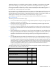
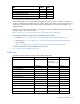
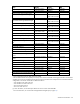
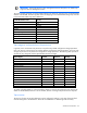
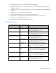
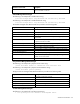
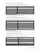
Table Of Contents
- HP Virtual Connect for c-Class BladeSystem Version 4.01 User Guide
- Abstract
- Notice
- Contents
- Introduction
- HP Virtual Connect Manager
- Virtual Connect domains
- Understanding Virtual Connect domains
- Managing domains
- Managing SNMP
- Viewing the system log
- Managing SSL configuration
- HP BladeSystem c-Class enclosures
- Virtual Connect users and roles
- Understanding VC administrative roles
- Managing users
- Local Users screen
- Configuring LDAP, RADIUS, and TACACS+
- Minimum requirements
- LDAP Server Settings (LDAP Server) screen
- LDAP Server Settings (LDAP Groups) screen
- LDAP Server Settings (LDAP Certificate) screen
- RADIUS Settings (RADIUS Server) screen
- RADIUS Settings (RADIUS Groups) screen
- TACACS+ Settings screen
- Role Management (Role Authentication Order) screen
- Role Management (Role Operations) screen
- Virtual Connect networks
- Understanding networks and shared uplink sets
- Managing networks
- Network Access Groups screen
- Define Network Access Group screen
- Ethernet Settings (Port Monitoring) screen
- Ethernet Settings (Advanced Settings) screen
- Quality of Service
- IGMP Settings (IGMP Configuration) screen
- IGMP Settings (Multicast Filter Set) screen
- Define Ethernet Network screen
- Ethernet Networks (External Connections) screen
- Ethernet Networks (Server Connections) screen
- Managing shared uplink sets
- Virtual Connect fabrics
- Virtual Connect server profiles
- Understanding server profiles
- Managing MAC, WWN, and server virtual ID settings
- Managing server profiles
- Define Server Profile screen
- Creating FCoE HBA connections for a BL890c i4
- Limited Ethernet connections when using HP Virtual Connect Flex-10/10D modules
- Creating iSCSI connections
- Flex-10 iSCSI connections
- Define Server Profile screen (multiple enclosures)
- Multiple network connections for a server port
- Defining server VLAN mappings
- Fibre Channel boot parameters
- Server Profiles screen
- Edit Server Profile screen
- Assigning a server profile with FCoE connections to an HP ProLiant BL680c G7 Server Blade
- Unassigning a server profile with FCoE connections to an HP ProLiant BL680c G7 Server Blade and deleting the SAN fabric
- General requirements for adding FC or FCoE connections
- Define Server Profile screen
- Virtual Connect and Insight Control Server Deployment
- Virtual Connect modules
- Firmware updates
- Stacking Links screen
- Throughput Statistics screen
- Enclosure Information screen
- Enclosure Status screen
- Interconnect Bays Status and Summary screen
- Causes for INCOMPATIBLE status
- Ethernet Bay Summary (General Information) screen
- Ethernet Bay Summary (Uplink Port Information) screen
- Ethernet Bay Summary (Server Port Information) screen
- Ethernet Bay Summary (MAC Address Table) screen
- Ethernet Bay Summary (IGMP Multicast Groups) screen
- Ethernet Bay Summary (Name Server) screen
- Ethernet Port Detailed Statistics screen
- FC Port Detailed Statistics screen
- FC Bay Summary screen
- Interconnect Bay Overall Status icon definitions
- Interconnect Bay OA Reported Status icon definitions
- Interconnect Bay VC Status icon definitions
- Interconnect Bay OA Communication Status icon definitions
- Server Bays Summary screen
- Server Bay Status screen
- Port status conditions
- Interconnect module removal and replacement
- Virtual Connect modules
- Upgrading to an HP Virtual Connect 8Gb 24-Port FC Module
- Upgrading to an HP Virtual Connect 8Gb 20-Port FC Module
- Upgrading or removing an HP Virtual Connect Flex-10, HP Virtual Connect FlexFabric, or HP Virtual Connect Flex-10/10D module
- Upgrading to an HP Virtual Connect FlexFabric module from a VC-FC module
- Onboard Administrator modules
- Maintenance and troubleshooting
- Appendix: Using Virtual Connect with nPartitions
- Support and other resources
- Acronyms and abbreviations
- Documentation feedback
- Index
Virtual Connect domains 38
• The Cause string indicates why an object transitioned to the current managed state from the specific
objects perspective. A network failure is an example Cause string.
• The RootCause string indicates the root causes for an object transitioning managed states. The
RootCause for a network failure could indicate all uplink ports of the network have failed.
• The ReasonCode provides an object specific reason for the managed state transition. The reason codes
are unique between objects, allowing more specific actions to be taken programmatically from SNMP
management stations.
vcDomainManagedStatusChanged
The following is an example of a domain Cause string:
2 of 7 profiles contain unmapped connections in the domain
The following is an example of a domain RootCause string:
Modules not redundantly connected, failure of module enc0:iobay1 or
enc0:iobay2 or enc1:iobay2 will isolate some modules; Port enc0:iobay5:d3:v1
loop detected and automatically disabled
The domain managed status ReasonCodes are provided in the following table.
Domain reason code Description
vcDomainOk
All enclosures and profiles are normal in the domain.
vcDomainAbnormalEnclosuresAndProfil
es
One or more enclosures and profiles are abnormal in the domain.
vcDomainSomeEnclosuresAbnormal
At least one enclosure is not OK or Degraded.
vcDomainUnmappedProfileConnections
The profile contains connections that are not mapped to a server port.
vcDomainStackingFailed
All stacking links between one or more modules have failed.
vcDomainStackingNotRedundant
Some stacking links between one or more modules have failed, but
connectivity still exists between modules.
vcDomainSomeProfilesAbnormal
One or more profiles in the domain are abnormal.
vcDomainUnknown
The condition of the domain cannot be determined.
vcDomainOverProvisioned
More than 16 VC modules are in the domain.
vcEnclosureManagedStatusChanged
The following is an example of a enclosure Cause string:
2 of 6 Ethernet modules are abnormal in enclosure enc0
The following is an example of a enclosure RootCause string:
Module in bay enc0:iobay3 has been removed
The enclosure managed status ReasonCodes are provided in the following table.
Enclosure reason code Description
vcEnclosureOk
The enclosure is normal.
vcEnclosureAllEnetModulesFailed
All Ethernet modules are abnormal, none are OK or degraded.
vcEnclosureSomeEnetModulesAbnormal
One or more Ethernet modules are abnormal.
vcEnclosureSomeModulesOrServersInco
mpatible
The enclosure contains incompatible modules, or configured modules
are missing.
vcEnclosureSomeFcModulesAbnormal
One or more FC modules are abnormal.
vcEnclosureSomeServersAbnormal
At least one server is in a known state and no servers are OK, or at
least one server is degraded.