HP Virtual Connect Manager Command Line Interface for c-Class BladeSystem Version 3.10/3.15 User Guide Abstract This document contains user information for the HP Virtual Connect Manager Version 3.10/3.15 Command Line Interface. This document is for the person who installs, administers, and troubleshoots servers and storage systems. HP assumes you are qualified in the servicing of computer equipment and trained in recognizing hazards in products with hazardous energy levels.
© Copyright 2010, 2011 Hewlett-Packard Development Company, L.P. The information contained herein is subject to change without notice. The only warranties for HP products and services are set forth in the express warranty statements accompanying such products and services. Nothing herein should be construed as constituting an additional warranty. HP shall not be liable for technical or editorial errors or omissions contained herein. Confidential computer software.
Contents Introduction .................................................................................................................................. 5 What's New ................................................................................................................................................ 5 Changes from VC 3.10 to 3.15........................................................................................................... 5 Changes from VC 3.00 to 3.10.................................
server-port ....................................................................................................................................... 62 server-port-map ................................................................................................................................ 62 snmp............................................................................................................................................... 64 snmp-trap ....................................................
Introduction What's New The command line interface user guide contains the following changes for VC 3.
Command Changes Virtual Connect 3.10 Virtual Connect 3.15 set fabric 10Gb/24-Port Module supports both the Auto and Manual Login Re-Distribution schemes, whereas other FC modules only support the Manual Login Re-Distribution scheme. 10Gb/24-Port Module is present in the help file, but it is not supported. Module, HP VC 4Gb FC Module, HP VC 8Gb 20-Port FC Module, and HP VC 8Gb 24-Port FC Module only support the Manual Login Re-Distribution scheme.
Command Changes Virtual Connect 3.00 Virtual Connect 3.10 "Secondary". Boot Priority is set to either Primary or Secondary remove interconnect The "remove The remove interconnect" interconnect command is no longer supported. Not supported help iscsi-boot-param Added support for "iscsi-boot-param," which enables the user to set and show iSCSI boot parameters of a specified iSCSI connection.
HP VC FlexFabric 10Gb/24-Port module is not supported in VC 3.10, still we can see many instances where this module has been specified in help file. Virtual Connect overview Virtual Connect is a set of interconnect modules and embedded software for HP BladeSystem c-Class enclosures that simplifies the setup and administration of server connections.
domain, any server blade can access any LAN or SAN connected to a VC module, and a server blade can be used as a spare for any server blade within the same enclosure. By stacking (cabling) the Ethernet or FlexFabric modules within the domain and connecting the FC or FlexFabric modules to the same set of FC SANs, every server blade in the domain can be configured to access any external network connection.
Command line syntax CLI input is case-insensitive except when otherwise noted.
The general format of a CLI option is as follows: -
commands. Supporting comments and blank lines enables users to maintain descriptive comments and notes in the configuration script more easily. When using a Linux SSH client, simply redirect the script into SSH. If the SSH keys are not configured on the client and in the firmware, a password prompt appears. To allow script automation and better security, SSH public/private key-pairs can be generated and uploaded to the public key to the VC firmware. >ssh Admin@192.168.0.120 < myscript.
# Create a Shared Uplink Port Set add uplinkset SharedSet1 # Assign a profile to a device bay assign profile MyProfile enc0:1 # Done!!! Unassigning multiple profiles In previous firmware releases, if the user needed to unassign multiple profiles from several device bays, the unassign profile command could be used at the command line. When many profiles need to be unassigned, sending a command for each server profile to be unassigned can be tedious.
GETTING STARTED: help : displays a list of available subcommands exit : quits the command shell ? : displays a list of managed elements for a subcommand ? : displays detailed help for a command -> Non-Interactive Mode In some cases, users might want to write automated scripts that execute a single command at a time. These scripts can be used to batch several commands in a single script file from the SSH client.
Example 3: Displaying all external uplink that have a link established ->show uplinkport status=linked Example 4: Displaying all uplink ports with connector type of RJ-45 and speed configured to Auto ->show uplinkport type=RJ45 Speed=Auto Example 5: Displaying all servers currently powered on ->show server power=On Introduction 15
Command line Subcommands Command Description add Add a new object to the domain or to another object assign Assign a server profile to a device bay delete Delete the domain configuration exit Exit the Virtual Connect Manager command-line shell help Display context-sensitive help for a command or object import Import an enclosure into the domain load Transfer a file from a remote location to the domain poweroff Power off one or more servers poweron Power on one or more servers reboot Reb
Managed element Description firmware (on page 36) Manage interconnect module firmware igmp (on page 36) interconnect (on page 37) iscsi-boot-param (on page 38) iscsi-connection (on page 41) ldap (on page 43) ldap-certificate (on page 44) ldap-group (on page 45) link-dist-interval (on page 47) log-target (on page 48) mac-cache (on page 50) network (on page 50) port-monitor (on page 53) profile (on page 56) server (on page 58) serverid (on page 61) server-port (on page 62) server-port-map (on page 62) snm
all Manage all Virtual Connect domain elements. Supported actions: help, show Item Description show all Display all Virtual Connect domain configuration objects. This command is typically useful for displaying a snapshot of the entire domain configuration with a single command. show all [*] Syntax Examples ->show all Displays all configuration objects (summary view) ->show all * Displays all configuration objects (detailed view) devicebay Manage general enclosure device bay settings and information.
domain Manage general Virtual Connect domain settings and information. Supported actions: delete, help, set, show Item Description delete domain Delete the existing Virtual Connect domain configuration. Deleting the domain removes the entire Virtual Connect domain configuration and resets it to the original defaults. After the domain has been deleted, you are logged out and the Virtual Connect Manager resets. delete domain [-quiet] Syntax Option quiet Examples Suppresses user confirmation prompts.
Item Description MacType (optional) The type of MAC address source to use for assignment. Valid values include "VC-Defined", "Factory-Default", and "User-Defined". MacPool (optional) The pre-defined MAC pool to use for address assignment. Valid values include integers 1-64. This property is only valid if the MacType is set to "VC-Defined". If not specified, the default pool ID is 1.
Item Description Sets the WWN address source to a custom, user-defined address range ->set domain SingleDense=true Sets the display option to support single-dense servers in a double-dense supported configuration Item Description show domain Display general Virtual Connect domain information, including the Virtual Connect domain name, the VCM domain IP address settings, and MAC/WWN address settings for the domain.
Item Description ->import enclosure UserName=Administrator Password=fgg7h*1 DoubleDense=true Imports the local enclosure with a double-dense device bay display format -> import enclosure 192.168.0.120 UserName=MyOaUser Password=dgfsfdsjd Imports a remote enclosure into the domain -> import enclosure Imports the local enclosure that is already discovered -> import enclosure 192.168.0.
Item Description add enet-connection Add a new Ethernet network connection to an existing server profile. The maximum number of Ethernet connections that can be added to a server profile is 128.
Item Description Adds a new Ethernet network connection and uses factory default addresses ->add enet-connection MyNewProfile AddressType=User-Defined EthernetMAC=00-17-A4-77-00-00 iScsiMAC=00-17-A4-77-00-01 Adds a new Ethernet network connection and provides user-defined MAC addresses ->add enet-connection MyProfile Network=MyNetwork SpeedType=Preferred Adds a new Ethernet network connection and sets the speed to "Preferred" ->add enet-connection MyProfile Network=MyNetwork SpeedType=Custom Speed=2000 Add
Item Description Speed (required if the SpeedType is Custom) The user-defined speed for the server port. Valid values include 100Mb to MAX configured speed for the network in 100Mb increments.
Item Description uplink sets can transmit and receive untagged frames only. The "Map" option enables the user to add more than one network to a single Ethernet port for the server profiles, and also enables the user to specify VLAN mapping between server tags and VC networks. Also, Ethernet networks with dedicated uplinks can transmit and receive untagged frames only.
Item Syntax Option quiet Properties UserName (optional) MacType (optional) MacStart (required if the MacType is User-Defined) MacEnd (required if the MacType is User-Defined) WwnType (optional) WwnStart (required if the WwnType is User-Defined) WwnEnd (required if the WwnType is User-Defined) ServerIdType (optional) Description MacType, WwnType, and ServerIdType.
Item Description serverIdStart=VCX0000000 serverIdEnd=VCX00000ZZ Removes the external manager and releases the profile control Item Description set external-manager Enable or disable an existing external manager’s control of the Virtual Connect domain. set external-manager [-quiet] UserName= Syntax Enabled= Option quiet This option suppresses user confirmation prompts and is useful when scripting operations.
Item Description to ports X1, X2, X3, and X4, respectively. Speed (optional) The port speed for the uplink ports in the fabric. Valid values include "Auto", "2Gb", "4Gb', and "8Gb". The default port speed is "Auto". Speed restrictions: • • LinkDist (optional) Examples Item remove fabric For the HP 4Gb VC-FC Module and HP Virtual Connect 4Gb FC Module, valid speed values include "Auto", "2Gb", and "4Gb".
Item Description "4Gb", and “8Gb”. The default port speed is “Auto”. Speed restrictions: • • For the HP 4Gb VC-FC Module and HP Virtual Connect 4Gb FC Module, valid speed values include "Auto", "2Gb", and "4Gb". For the HP VC 8Gb 24-Port FC Module, HP VC 8Gb 20-Port FC Module, and HP VC FlexFabric 10Gb/24-Port Module valid speed values include "Auto","2Gb","4Gb", and "8Gb". LinkDist (optional) Specifies the login re-distribution scheme for load balancing. Valid values include "Auto" and "Manual".
Item Syntax Description connections (on page 119)." add fc-connection [Fabric=] [Speed=] [AddressType=] [PortWWN=] [NodeWWN=] Parameter ProfileName (required) The name of an existing profile to which the new connection is added Properties Fabric (optional) Speed (optional) The name of an existing fabric to associate with the connection.
Item Description ProfileName (required) The name of an existing profile from which the last FC connection is to be removed Example ->remove fc-connection MyProfile Removes an FC connection from a profile Item Description set fc-connection Modify an existing FC SAN connection.
Item Description ->set fc-connection BlueProfile 1 BootPriority=Primary BootPort=50:06:0B:00:00:C2:62:00 BootLun=5 Changes the SAN boot priority and sets additional boot parameters Item Description show fc-connection Display the FC SAN connections associated with the server profiles. Syntax show fc-connection [] Parameter ConnectionID (optional) Examples The ID of an existing FC SAN connection. The ID format is .
Item Description (optional) new connection. If not specified, the default is the domain default. If "UserDefined" is specified, then both a Port WWN and Node WWN must also be specified. Valid values include "Factory-Default" and "User-Defined". PortWWN (required if WWNAddressType is User-Defined) NodeWWN (required if WWNAddressType is User-Defined) MACAddressType (optional) The user-defined Port WWN address to use for the connection. The PortWWN must be an unused WWN address.
Item Description set fcoe-connection Modify an existing FCoE connection. set fcoe-connection [Fabric=] [SpeedType=<1Gb|2Gb|4Gb|8Gb|Custom|Disabled>] [CustomSpeed=<100Mb-10Gb>] [BootPriority=] [BootPort=] [BootLun=] Syntax Parameters ConnectionID (required) Properties Fabric (optional) The ID of an existing FCoE connection. The ID format is . The name of the FCoE SAN fabric to associate with the connection.
Item Parameter ConnectionID (optional) Examples Description The ID of an existing FCoE connection. The ID format is . can be used to display all the FCoE connections of a profile. '*' displays all the FCoE connections existing in the domain.
Item Description show igmp Display Ethernet IGMP Snooping settings. show igmp Syntax Example ->show igmp Displays IGMP Snooping settings interconnect Manage I/O interconnect modules. Supported actions: help, remove, show Item Description remove interconnect Remove an interconnect module from the domain. Normally this command is used if a module has been physically removed from the enclosure. To be removed, the module must not be currently in use by any element in the domain.
Item Description interconnect bay number 5 ->show interconnect enc0:* Displays interconnect modules in all bays of a specific enclosure ->show interconnect enc0:3 Displays detailed information on a specific interconnect module in interconnect bay 3 of the primary enclosure iscsi-boot-param Manage iSCSI boot parameters within a domain. Supported actions: help, remove, set, show Item Description remove iscsi-boot-param Remove all iSCSI boot parameters configured on the specified iSCSI connection.
Item Description Properties BootOrder (optional) Enables or disables iSCSI boot. To enable iSCSI boot, select Primary, Secondary, or USE-BIOS. The default selection for this attribute is Disabled. LUN (optional) The LUN of the Target identifies the volume to be accessed. Valid values for standard LUNs are 0 to 255 decimal. Valid values for extended LUNs are 13- to 16-character hexidecimal values. The default is 0.
Item Description MutualUsername (required if authentication type is CHAPM) MutualSecret (required if authentication type is CHAPM) The mutual user name for CHAPM authentication. The user name length is a maximum of 223 characters. If the name contains non-alphanumeric characters, it must be enclosed in double quotation marks. ISCSIBootParamDHCP (optional) Enables the iSCSI option ROM to retrieve the iSCSI boot parameters from DHCP or through static configuration.
Item Examples Description ->show Displays ->show Displays ->show Displays iscsi-boot-param MyProfile1:1 boot parameters configured on connection 1 of MyProfile1 iscsi-boot-param MyProfile1:* boot parameters configured on all connections of MyProfile1 iscsi-boot-param * boot parameters configured on all profiles in the domain iscsi-connection Manage iSCSI connections.
Item Description ->add iscsi-connection MyNewProfile Adds a new iSCSI connection and leaves it unassigned ->add iscsi-connection MyNewProfile AddressType=Factory-Default Adds a new iSCSI network connection and uses factory-default addresses ->add iscsi-connection MyNewProfile AddressType=User-Defined iScsiMAC=00-17-A4-77-00-00 Adds a new iSCSI network connection and provides a user-defined MAC address ->add iscsi-connection MyProfile Network=MyNetwork SpeedType=Preferred Adds a new iSCSI network connection
Item Description Examples ->set iscsi-connection MyNewProfile:1 Network=SomeNetwork Changes the network to a different one ->set iscsi-connection MyNewProfile:1 Network="" Unassigns the network from the connection ->set iscsi-connection MyProfile:1 Network=MyNetwork SpeedType=Preferred Modifies the speed to Preferred ->set iscsi-connection MyProfile:1 SpeedType=Custom Speed=2000 Modifies the iSCSI connection and sets the speed to 2Gb Item Description show iscsi-connection Display the iSCSI connections
Item Description Properties Enabled (optional) Enables or disables LDAP authentication. Valid values include "true" and "false". LocalUsers (optional) Enables or disables local user authentication. Valid values include "Enabled" and "Disabled". WARNING: Disabling local users without correctly configuring LDAP authentication first may result in not being able to log on. Enabling and disabling local user authentication requires you to be logged in as an LDAP user.
Item Description Address (required) A valid IP address or host name of the FTP server, including user name and password Filename (required) The name of the certificate file on the server. Example ->load ldap-certificate Address=ftp://user:password@192.168.10.12 filename=/new-ldap.crt Downloads LDAP certification from the remote FTP server Item Description remove ldap-certificate Remove an existing LDAP certificate.
Item Description add ldap-group Add a new directory group to the directory services configuration. Syntax add ldap-group [Description=] [Privileges=domain,server,network,storage] Parameters GroupName (required) The name of the LDAP directory group to add Properties Description (optional) An informational description for the new group to be added Privileges (optional) A set of one or more privileges for the group.
Item Description Modifies a directory group description and privileges Item Description show ldap-group Display the existing directory groups. Syntax show ldap-group [|*] Parameter GroupName (optional) The name of an existing LDAP group in the domain. If "*" is specified, then all LDAP groups appear. The default behavior, if not specified, is to display a summary of all groups.
log-target Manage remote log destination settings. Supported actions: add, help, remove, set, show, test Item Description add log-target Add a new remote log destination. Syntax add log-target [Severity=] [Transport=] [Port=<1-65535>] [Security=] [Format=] [State=] Properties Destination (required) The IpAddress or the DNS of the remote log destination that has been configured.
Item Description [Security=] [Format=] [State=] Parameter ID (required) Properties Destination (optional) Severity (optional) The index of the remote log destination whose configuration needs to be modified The IpAddress or the DNS of the remote log destination that has been configured Severity of the log messages that should be sent to the specified destination. Valid values include "Critical", "Error", "Warning", and "Info". The default value is "Info".
mac-cache Manage Ethernet MAC Cache failover settings. Supported actions: help, set, show Item Description set mac-cache Modify Ethernet MAC Cache failover settings. set mac-cache [Enabled=] [Refresh=] Syntax Properties Enabled (optional) Refresh (optional) Examples Enables or disables MAC cache failover. Valid values include "true" and "false". The refresh interval for the MAC Cache (in seconds). Valid values include integers from 1-30. The default refresh interval is 5 seconds.
Item Properties UplinkSet (optional) Description The name of an existing shared uplink port set to use with this new network. If this property is specified, then a valid VLAN ID must also be provided. The limit is 32 networks per shared uplink set. VLanID (optional) The VLAN ID associated with the network (used with shared uplink port set only). The VLAN ID is a valid number between 1 and 4094. State (optional) Enables or disables the network. Valid values are "Enabled" and "Disabled".
Item Description remove network Syntax Remove a network from the domain. To remove a network, it must not be in use by any server profiles. remove network Parameter NetworkName (required) The name of an existing network in the domain. A network name of "*" removes all networks. Examples ->remove network MyNetwork Removes a network ->remove network * Removes all networks Item Description set network Modify an existing Ethernet network.
Item Description PrefSpeed (Required if PrefSpeedType is 'Custom') MaxSpeedType (Optional) The connection speed for any Ethernet connection attached to this network. Valid values range from 100Mb to 10Gb in 100Mb increments. MaxSpeed (required if MaxSpeedType is "Custom) Examples Maximum connection speed for any Ethernet connection attached to this network. Valid values include "Unrestricted" and "Custom". "Custom" enables the user to configure the preferred speed. The default value is "Unrestricted".
Item Description add port monitor Add a new network analyzer port and other ports to be monitored. add port-monitor [AnalyzerPort=] [Speed=] [Duplex=] [MonitorPort=] [Direction=] Syntax Properties AnalyzerPort (optional) The uplink port that is used for monitoring network traffic. Only one port can be configured as the analyzer port.
Item Description Removes all network analyzer ports from the configuration ->remove port-monitor monitorPort=enc0:1:1 Removes a specific server port from the monitored port list ->remove port-monitor monitorPort=* Removes all monitored ports Item Description set port-monitor Modify an existing port monitor configuration.
profile Manage server profiles. Supported actions: add, assign, help, remove, set, show, unassign Item Description add profile Create a new server profile. After the profile has been created, the profile can then be configured using the "set" subcommand, and the additional network, fabric, and FCoE connections can also be added. The server profile can also be assigned to a device bay using the "assign" subcommand.
Item Description Creates a new profile and uses the factory assigned serial number ->add profile MyNewProfile SNType=User-Defined SerialNumber=VCX0113121 UUID=15713c60-fcf2-11dc-a656-0002a5d5c51b Creates a new profile and specifies a custom virtual serial number and UUID Item Description assign profile Assign a server profile to a device bay.
Item Description Examples ->set profile MyProfile Name=MyNewProfileName Changes the name of a server profile ->set profile Profile1 EFIState=absent Removes EFI partition block information from a profile Item Description show profile Syntax Display all server profiles that exist in the domain and a summary of the associated Ethernet, iSCSI, FC, and FCoE connections.
Item Description displayed by the show server command. Options Force Forces a power off operation without waiting for the OS to shutdown gracefully. This option should only be used as a last resort because it can cause potential data loss on the server. ForceOnTimeout Attempts a graceful shutdown, but if the server does not shut down within the timeout period (default is 60 seconds), then the server is forced to power off.
Item Description Powers on a specific multi-blade server that occupies bays 1-4 of the primary enclosure Item Description reboot server Reboot one or more physical servers. reboot server [-Force] [-ForceOnTimeout] [-timeout= Syntax Parameter ServerID (required) Options Force The reference ID of a server in the domain. The format of the server ID is . If the Enclosure ID is not provided, then the primary or local enclosure (enc0) is used by default.
Item Description Displays detailed information for all servers ->show server enc2:* Displays detailed information for all servers in a specific enclosure ->show server enc0:4 Displays detailed information for the specific server in device bay 4 of an enclosure named "MyEnclosure" ->show server enc0:5 Displays detailed information for a specific multi-blade server that occupies bays 5-8 of the primary enclosure serverid Manage virtual Server ID configuration settings.
Item Description show serverid Display virtual server ID configuration properties. show serverid Syntax Example ->show serverid Displays virtual server ID configuration properties server-port Display the physical server ports. Supported actions: help, show Item Description show server-port Display physical server port information. show server-port [] Syntax Parameter PortID (Optional) Examples The reference of a port mapping ID. The PortID format is EnclosureID:IOBay:Port.
Item Description be configured once for every profile connection, and every profile connection can be configured for a maximum of 28 networks. Properties Uplinkset (optional) The name of the shared uplinkset to use with the server port mapping. If the domain setting SharedServerVLanId is set to "true", then the Uplinkset is a required value. VLanID (optional) The VLAN ID to be used for the mapping. Valid values include 1 to 4094.
Item Description (required) server port. The format of the ConnectionId is . Network (required) The name of a valid Ethernet network on which the mapping exists Properties VLanID (optional) Untagged (optional) Examples Item The new VLAN ID to be used for the mapping server port to network. Valid values include 1 to 4094. Enables or disables the network to handle untagged packets. Only one network in an Ethernet network connection is allowed to handle untagged packets.
Item Description Properties ReadCommunity (optional) Read-Only Community String for the SNMP configuration. The default value is "public". If the type is "Enet", the maximum length of the read community string is 39 characters. If the type is FC, the maximum length is 12 characters. SystemContact (optional) SNMP system contact information. Enabled (optional) Enables or disables the SNMP agent. The default value is "true". Valid values include "true" or "false".
Item Description category|All|None>][FcCategories=] Parameter Name (required) A unique name for the new trap being added Properties Address (required) IPv4 address or DNS name for the trap destination Format Format of the new trap. Valid values are "SNMPv1" and "SNMPv2". The default is "SNMPv1" if not specified. Severities Trap severities to send to the destination. Valid values are "Normal", "Unknown", "Info", "Warning", "Minor", "Major", "Critical", "All", and "None".
Item Description ->remove snmp-trap * Removes all configured SNMP trap destinations Item Description set snmp-trap Modifies an existing SNMP trap destination set snmp-trap [Name=][Address=][Community=][Format=][Severity=][DomainCategory=][EnetCategory=][FcCategory=] Syntax Parameter Tr
Item Examples Description ->show Displays ->show Displays snmp-trap MyTrap1 the SNMP trap configuration for a single trap snmp-trap * all configured SNMP traps Item Description ->test snmp-trap Generates an SNMP test trap and sends it to all configured destinations.
Item Description Syntax show ssh Example ->show ssh Displays the SSH key configuration ssl Allow or disallow weak SSL encryption (browser/SOAP). Supported actions: set, show, help Item Description set ssl Allow modifications to be made to the SSL configuration, and enable or disable string encryption for SSL communication with the web server. set ssl Strength=[] Syntax Property Strength (required) Examples The strength of the encryption cipher. Valid values include "All" and "Strong".
Item Description Filename (required) The name of the certificate file on the remote FTP server Example ->load ssl-certificate Address=ftp://user:password@192.168.10.12 Filename=my-new-ssl.crt Transfers a new custom SSL Certificate from the remote FTP server Item Description show ssl-certificate Display the Virtual Connect web server SSL certificate information.
Item Description Syntax show stackinglink ->show stackinglink Displays a summary listing of all stacking links and status Example statistics Manage statistics for interconnect module ports. Supported actions: help, reset, show Item Description reset statistics Reset per-port statistics for the specified port ID. reset statistics Syntax Parameter PortID (required) The port ID on which to reset statistics.
Item Description DCBX Pending Status DCBX Priority Flow Control State DCBX Priority Group State DCBX Application Protocol State Item Description disabled The feature is operationally disabled. ok The feature is configured properly, or DCBX negotiation is in progress. incompatible cnfg Flex Fabric Network Adapter has an incompatible configuration and is not willing to accept changes.
Item Description ->save supportinfo address=tftp://192.168.10.12 Saves a support information file to a remote TFTP server ->save supportinfo address=ftp://user:password@192.168.10.12 Saves a support information file to a remote FTP server systemlog View the Virtual Connect Manager system event log. Supported actions: help, show Item Description show systemlog Display the Virtual Connect manager system log.
Item Description "::". Properties Network (required) The name of an existing network to which the port is added if the uplink set name has not been specified. UplinkSet (required) The name of an existing shared uplink port set to which the port is added if the network name has not been specified. Speed (optional) Specifies the port speed for the port (optional). Valid values include "Auto", "10Mb", "100Mb", "1Gb", "10Gb", and "Disabled".
Item Description Parameter PortID (required) The ID of the port to modify. The specified port must already be added to a network or uplink port set. The port ID is in the format :: Properties Network (required) The name of the network to which the port belongs if the uplink set name is not specified. UplinkSet (required) The name of the shared uplink port set to which the port belongs if the network name is not specified.
Item Description ->show Displays ->show Displays uplinkport status=Linked all the uplink ports that are linked uplinkport ID=enc0:1 type=RJ45 all the uplink ports for the specific bay 1 with connector type RJ-45 uplinkset Manage shared uplink port sets Supported actions: add, help, remove, set, show Item Description add uplinkset Syntax Create a new shared uplink port set.
Item Description Examples ->set uplinkset Blue Name=Red Changes the name of an shared uplink set from "Blue" to "Red" ->set uplinkset Blue connectionMode=Failover Changes the connection mode of the uplink set Item Description show uplinkset Syntax Display shared uplink configurations. show uplinkset [ | *] Parameter UplinkSetName (optional) Name of an existing uplink port set. "*" displays a detailed view of all the uplink port sets.
Item Description ->add user bill Password=HGtwf7272562 Privileges="domain,network" FullName="Bill Johnson" ContactInfo=billj@company.com Enabled=true Adds a new user and configures additional user properties ->add user Admin Password=hjkhfd Privileges=* Adds an "Admin" user with all privileges Item Description remove user Remove a user from the Virtual Connect Manager database. remove user Syntax Parameter UserName (required) Examples The name of an existing user that will be removed.
Item Description show user Display user summary or user details. Syntax Parameter UserName (optional) Examples show user [] Name of an existing user in the VC domain. If not specified, then summary of all existing user will be displayed. ->show user Lists all existing users ->show user steve Displays details of an existing user by name ->show user * Displays details of all existing users user-security Manage local user security settings.
Supported actions: help, reset Item Description reset vcm Reset the Virtual Connect Manager. A failover to the standby VCM may also be specified (optional), if there is a standby VCM available. IMPORTANT: Resetting the VCM causes a temporary loss in connectivity with the Virtual Connect Manager. If failover is specified and there is a standby VCM, users are logged off and must reconnect using the standby VCM IP address.
assign profile MyProfile enc0:1 • Management element help—provides a listing of objects that are supported with a specific subcommand and a brief description of the management element and what it represents in the management model: ->help devicebay General Enclosure Device Bay settings and information Supported Subcommands: help show ----------------------------------------------------------------------->show devicebay -help Description: This command displays all device bays in the domain Syntax: show dev
• Scriptable output format The interactive user output format is the default. However, by using a command-line option, the user can also specify a "parse-friendly" output format, which provides data in a format that can be easily interpreted by automated scripts invoking the CLI. The different output formats primarily impact the show subcommand in the CLI infrastructure, where a majority of the informational details are displayed.
UserName Privileges FullName ContactInfo Enabled : : : : : steve domain,server,network,storage Steve Johnson steve.johnson@hp.com true Example 3: Stanza output format for displaying all user details ->show user * UserName : Administrator Privileges : domain,server,network,storage FullName : Steve Johnson ContactInfo : steve.johnson@hp.
Scriptable output format Scriptable output format allows scripts to invoke CLI commands and receive command responses that can be easily parsed by the scripts. This capability is provided by two options that are available: -output=script1 and -output=script2. These options are described in more detail below. To display output with no headers or labels, use no-headers as an additional output option value.
Administrator;domain,server,network,storage;Steve Johnson;steve.johnson@hp.com;true Admin;domain,server,network,storage;Admin;Admin;true steve;domain,server,network,storage;Steve Johnson;steve.johnson@hp.com;true Example 4: Scriptable output format displaying all users (no table header) ->show user -output=script2,no-headers Administrator;domain,server,network,storage;Steve Johnson;steve.johnson@hp.
Statistics descriptions Ethernet modules Ethernet uplink and downlink ports Name RFC Description rfc1213_IfInDiscards 1213 The number of inbound packets that were chosen to be discarded even though no errors had been detected to prevent their being deliverable to a higher-layer protocol. One possible reason for discarding such a packet could be to free up buffer space.
Name RFC Description rfc1213_IfOutOctets 1213 The total number of octets transmitted out of the interface, including framing characters. rfc1213_IfOutQLen 1213 The length of the output packet queue (in packets). rfc1213_IfOutUcastPkts 1213 The total number of packets that higher-level protocols requested be transmitted to a subnetwork-unicast address, including those that were discarded or not sent.
Name RFC rfc1213_Dot1dTpPortInFrame 1493 s rfc1757_StatsBroadcastPkts 1757 Description The number of frames that have been received by his port from its segment. Note that a frame received on the interface corresponding to this port is only counted by this object if and only if it is for a protocol being processed by the local bridging function, including bridge management frames.
Name RFC Description more other hosts (transmit collisions as defined by IEEE 802.3k) plus receiver collisions observed on any coax segments to which the repeater is connected. rfc1757_StatsDropEvents 1757 The total number of events in which packets were dropped by the probe due to lack of resources. This number is not necessarily the number of packets dropped; it is just the number of times this condition has been detected.
Name RFC Description octets). This object can be used as a reasonable estimate of Ethernet utilization. If greater precision is desired, the etherStatsPkts and etherStatsOctets objects should be sampled before and after a common interval. The differences in the sampled values are Pkts and Octets, respectively, and the number of seconds in the interval is Interval. These values are used to calculate the Utilization as follows: Pkts * (9.6 + 6.4) + (Octets * .
Name RFC Description framing bits but including FCS octets). rfc1757_StatsPkts65to127Oc 1757 tets The total number of packets (including bad packets) received that were between 65 and 127 octets in length inclusive (excluding framing bits but including FCS octets). rfc1757_StatsTXNoErrors 1757 All packets transmitted without error, less oversized packets.
Name RFC Description including those that were discarded or not sent. This object is a 64-bit version of ifOutUcastPkts. Discontinuities in the value of this counter can occur at re-initialization of the management system, and at other times as indicated by the value of ifCounterDiscontinuityTime.
Name RFC Description counter can occur at re-initialization of the management system, and at other times as indicated by the value of ifCounterDiscontinuityTime. rfc2665_Dot3ControlInUnkno 2665 wnOpcodes A count of MAC Control frames received on this interface that contain an opcode that is not supported by this device. Discontinuities in the value of this counter can occur at re-initialization of the management system, and at other times as indicated by the value of ifCounterDiscontinuityTime.
Name RFC Description of the management system, and at other times as indicated by the value of ifCounterDiscontinuityTime. rfc2665_Dot3StatsCarrierSen 2665 seErrors The number of times that the carrier sense condition was lost or never asserted when attempting to transmit a frame on a particular interface. The count represented by an instance of this object is incremented at most once per transmission attempt, even if the carrier sense condition fluctuates during a transmission attempt.
Name RFC Description represented by an instance of this object is incremented when the frameCheckError status is returned by the MAC service to the LLC (or other MAC user). Received frames for which multiple error conditions obtain are, according to the conventions of IEEE 802.3 Layer Management, counted exclusively according to the error status presented to the LLC. Note: Coding errors detected by the physical layer for speeds above 10 Mb/s will cause the frame to fail the FCS check.
Name RFC Description are not otherwise counted. Discontinuities in the value of this counter can occur at re-initialization of the management system, and at other times as indicated by the value of ifCounterDiscontinuityTime. rfc2665_Dot3StatsInternalMa 2665 cTransmitErrors A count of frames for which transmission on a particular interface fails due to an internal MAC sublayer transmit error.
Name RFC Description mechanism in the PLS Carrier Sense Function as described in IEEE Std. 802.3, 1998 Edition, section 7.2.4.6. This counter does not increment on interfaces operating at speeds greater than 10 Mb/s, or on interfaces operating in full-duplex mode. Discontinuities in the value of this counter can occur at re-initialization of the management system, and at other times as indicated by the value of ifCounterDiscontinuityTime.
Name RFC Description occurrence of an event that causes the PHY to indicate 'Data reception error' on the GMII. The count represented by an instance of this object is incremented at most once per carrier event, even if multiple symbol errors occur during the carrier event. This count does not increment if a collision is present. Discontinuities in the value of this counter can occur at re-initialization of the management system, and at other times as indicated by the value of ifCounterDiscontinuityTime.
Name RFC Description hardware problem between module and FC mezzanine card settings. fcFBSYFrames 4044 fcmPortClass2RxFbsyFrames - The number of times that F_BSY was returned to this port as a result of a Class 2 frame that could not be delivered to the other end of the link. This can occur when either the fabric or the destination port is temporarily busy. This counter will never increment for an F_Port.
Name RFC fcNumberOfflineSequence s FCMGM connUnitPortStatCountNumberOfflineS T-MIB equences - Count of Offline Primitive sequence received at this port. This is a Fibre Channel only stat. fcPrimitiveSeqProtocolError 4044 s Description fcmPortPrimSeqProtocolErrors - The number of primitive sequence protocol errors detected at this port. This count is part of FC-PH's Link Error Status Block (LESB). fcRxByteRate N/A Average receive byte rate (Byte/s) for sample period of once a second.
Name RFC Description numBBCreditZero FCMGMTMIB connUnitPortStatCountBBCreditZero Count of transitions in/out of BBcredit zero state. The other side is not providing any credit. numBytesRx N/A Total number of bytes received. numBytesTx N/A Total number of bytes transmitted. numCRCErrors FCMGMTMIB connUnitPortStatCountInvalidCRC Count of frames received with invalid CRC. This count is part of the Link Error Status Block (LESB). (FC-PH 29.8).
Name RFC Description numInvalidTransmission FCMGMTMIB Words connUnitPortStatCountInvalidTxWords Count of invalid transmission words received at this port. This count is part of the Link Error Status Block (LESB). numLRsRx FCMGMTMIB connUnitPortStatCountRxLinkResets Count of Link resets. This is the number of LRs received. This is a Fibre Channel only stat. numLRsTx FCMGMTMIB connUnitPortStatCountTxLinkResets Count of Link resets. This is the number LRs transmitted.
Name RFC Description port numRxLCs N/A numRxOfflineSequence FCMGMTMIB s Number of link control frames received at this port connUnitPortStatCountRxOfflineSequenc es - Count of Offline Primitive OLS received at this port rxBytePeakRate N/A Receive max byte rate since last reset (bytes/sec) rxByteRate N/A Receive instantaneous byte rate (bytes/sec) rxFramePeakRate N/A Receive max frame rate since last reset – (frames/sec) rxFrameRate N/A Receive instantaneous frame rate (frames/sec) samplin
Object type connUnitPortStatCountRxElements Description The number of octets or bytes that have been received by this port in 1-second periodic polling of the port. This value is saved and compared with the next polled value to compute net throughput. For Fibre Channel, ordered sets are not included in the count.
FRAMESRECEIVED Object type connUnitPortStatCountRxObjects Description The number of frames, packets, IOs, and so on that have been received by this port. A Fibre Channel frame starts with SOF and ends with EOF. FC loop devices should not count frames passed through. This value represents the sum total for all other Rx objects.
Object type connUnitPortStatCountLinkFailures Description The number of link failures. This number is part of the LESB. (FC-PH 29.8). ::= { connUnitPortStatEntry 39 } LINKRESETRECEIVED Object type connUnitPortStatCountRxLinkResets Description The number of link resets. This is the number of LRs received. ::= { connUnitPortStatEntry 33 } LINKRESETTRANSMITTED Object type connUnitPortStatCountTxLinkResets Description The number of link resets. This is the number LRs transmitted.
Object type connUnitPortStatCountPrimitiveSequenceProtocolErrors Description The number of primitive sequence protocol errors detected at this port. This number is part of the LESB. (FC-PH 29.8). ::= { connUnitPortStatEntry 42 } PRJTFRAMES Object type connUnitPortStatCountPRJTFrames Description The number of times that FRJT is returned to this port as a result of a Frame that is rejected at the destination N_Port. This is the total for all classes.
Configuring the Virtual Connect domain using the CLI Basic configuration A Virtual Connect domain consists of an enclosure and a set of associated modules and server blades that are managed together by a single instance of the Virtual Connect Manager. The Virtual Connect domain contains specified networks, server profiles, and user accounts that simplify the setup and administration of server connections.
login as: password: Domain setup A Virtual Connect domain consists of an enclosure and a set of associated modules and server blades that are managed together by a single instance of the Virtual Connect Manager. the Virtual Connect domain contains specified networks, server profiles, and user accounts that simplify the setup and administration of server connections.
• Remove an existing user >remove user bob • Remove all local users except for the Administrator account >remove user * Display local users: • Summary display >show user • Detailed display >show user * • Display info on a single user >show user steve Up to 32 local user accounts can be created.
o Configure FC SNMP settings It is possible to create a user with no privileges. This user can only view status and settings. NOTE: The vcmuser_ account is an internal Onboard Administrator account created and used by Virtual Connect Manager to communicate with the Onboard Administrator. This account can show up in the Onboard Administrator system log. This account cannot be changed or deleted. Configuring LDAP authentication support for users • Set LDAP properties >set ldap serveraddress=192.168.0.
ships with default MAC addresses, Virtual Connect has the ability to assign MAC addresses that will override the factory default MAC addresses while the server remains in that Virtual Connect enclosure. When configured to assign MAC addresses, Virtual Connect securely manages the MAC addresses by accessing the physical NICs through the enclosure Onboard Administrator and the iLO interfaces on the individual server blades.
Creating an enet-network To create a new Ethernet network use the add network command: >add network MyNetworkName Modifying enet-network properties To modify Ethernet network properties, use the set network command: >set network MyNetworkName state=enabled name=NewName smartlink=enabled Displaying enet-networks To display Ethernet network properties, use the show network command: • Summary display >show network • Detailed display >show network * • Single network display > show network MyNetwork Add
IMPORTANT: If you are deploying a server where VLAN tags will be used (added) on the server itself, do not connect the server Ethernet port carrying VLAN-tagged traffic to a shared uplink set. Identifying an associated network as the native VLAN causes all untagged incoming Ethernet packets to be placed onto this network. Only one associated network can be designated as the native VLAN. All out-going Ethernet packets are VLAN tagged.
Fibre Channel setup To configure external Fibre Channel connectivity for the HP BladeSystem c-Class enclosure, do the following: 1. Identify WWNs to be used on the server blades deployed within this Virtual Connect Domain. 2. Define SAN fabrics. Configuring WWN address ranges • VC-Defined >set domain WwnType=VC-Defined WwnPool=5 • Factory-Default >set domain WwnType=Factory-Default Each server blade FC HBA mezzanine card ships with factory default port and node WWNs for each FC HBA port.
Configuring serial number ranges VC-defined > set serverid Type=VC-Defined PoolId=5 Factory-Default > set serverid Type=Factory-Default When using the HP-defined serial number ranges, be sure that each range is used only once within the environment. Server profile overview A Virtual Connect server profile is a logical grouping of attributes related to server connectivity and identity that can be assigned to a server blade.
MAC/WWN addresses, select a range of HP pre-defined or user-specified MAC addresses. See "Setting the domain name (on page 109)." IMPORTANT: Be sure to review the following list of guidelines before creating and deploying server profiles. • The server blade firmware and option card firmware must be at a revision that supports Virtual Connect profile assignment. See the HP website (http://www.hp.com/go/bladesystemupdates).
and SAN boot settings and connects the appropriate networks and fabrics. Server blades that have been assigned a profile and remain in the same device bay do not require further Virtual Connect Manager configuration during a server or enclosure power cycle. They boot and gain access to the network and fabric when the server and interconnect modules are ready.
set iscsi-boot-param MyProfile1:1 BootOrder=Primary Lun=100 InitiatorName="iqn.2009-09.com.someorg.iSCSI-Initiator" InitiatorIp=192.128.3.1 Mask=255.255.0.0 TargetName="iqn.2009-09.com.someorg.iSCSI-Target" TargetIp=192.128.3.
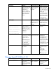
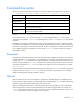
2 Start with modules in Bays 3-6, create a profile, then edit the profile and add connections Port 1 2 3 4 Connected to Bay 3 Bay 4 Bay 5 Bay 6 — Bay 3 Bay 5 — — Bay 4 Bay 6 — Port Connected to 1 Bay 3 2 Bay 4 3 Bay 5 4 Bay 6 5 Bay 3 6 Bay 4 7 Bay 5 8 Bay 6 Add connection, 4 times 3 Start with modules in Bays Port 3 and 4, create a profile, 1 hotplug modules into Bays 2 5 and 6, then edit the profile and add connections Connected to Bay 3 Bay 4 — Bay 3 Bay 5 — — Bay 4 Bay 6 — Port Connected to 1
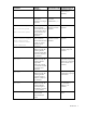
7 Start with modules in Bays Port 5 and 6, create a profile, 1 hotplug modules into Bays 2 3 and 4, then edit the profile Connected to Bay 5 Bay 6 — Bay 3 Bay 5 — — Bay 4 Bay 6 — Add connection is disallowed because the current FC module configurations do not match the existing connections in the profile.
Assigning a server profile to device bay 1 To assign a server profile to a specific device bay, use the assign profile command: >assign profile MyProfile enc0:1 When a profile is created and assigned to a multi-blade server, the profile is applied to all of the blades in the multi-blade server. Therefore, the profile should contain enough Ethernet and Fibre Channel connection entries for all of the ports on all of the blades in the multi-server.
• Assigning a VC-defined WWN • Changing the Fibre Channel boot parameters IMPORTANT: For Virtual Connect v2.1x, the server blade must be powered off for all profile changes if a Flex-10 NIC is installed in the server, and the server is connected to an HP Virtual Connect Flex-10 Module or to an empty bay. If any of the listed settings are changing, the server must be powered off before the profile action can occur. If the server blade is not powered off, a message appears and no changes are made.
• • Changing a connection's network: o From a single network to another single network o From a single network to multiple networks o From multiple networks to a single network Modifying the networks or VLAN IDs in a connection with multiple networks With Virtual Connect Manager v2.
Operation Examples Display overall domain status >show status Display stacking link configuration and status >show stackinglink Display the system log >show systemlog Display a list of servers in the domain • • Display server profiles Summary display >show server Detailed display >show server * • Single server display >show server enc0:1 • Summary display >show profile • • Detailed display >show profile * Delete the domain configuration Single profile display >show profile MyProfile >del
Virtual Connect Manager not found at this IP address. If the user attempts to log in to the secondary I/O bay, they might receive the following error message during the attempted login: Unable to communicate with the Virtual Connect Manager. Please retry again later. The login should succeed after the Virtual Connect Manager has restarted on this secondary Virtual Connect Ethernet module. Allow up to 5 minutes, depending on the enclosure configuration.
Technical support Before you contact HP Be sure to have the following information available before you call HP: • Technical support registration number (if applicable) • Product serial number • Product model name and number • Product identification number • Applicable error messages • Add-on boards or hardware • Third-party hardware or software • Operating system type and revision level HP contact information For United States and worldwide contact information, see the Contact HP website (h
Acronyms and abbreviations CHAP Challenge Handshake Authentication Protocol CRC cyclic redundant checks DCBX Datacenter Bridging Capability Exchange protocol DHCP Dynamic Host Configuration Protocol DNS domain name system EFI extensible firmware interface FC Fibre Channel FCoE Fibre Channel over Ethernet HBA host bus adapter IGMP Internet Group Management Protocol iSCSI Internet Small Computer System Interface LDAP Lightweight Directory Access Protocol Acronyms and abbreviations 128
LESB Link Error Status Block LUN logical unit number MAC Media Access Control PXE Preboot Execution Environment SAN storage area network SOAP Simple Object Access Protocol SSH Secure Shell SSL Secure Sockets Layer UDP User Datagram Protocol UUID universally unique identifier VC Virtual Connect VCM Virtual Connect Manager WWN World Wide Name WWPN worldwide port name Acronyms and abbreviations 129
Index A adding FC connections 119 adding FCoE connections 119 all 18 assigned MAC addresses 112 authorized reseller 127 B basic configuration 108 C CLI command execution modes 13 command batching 11 Command line 16 command line overview 9 command line syntax 10, 11, 13 Command output filtering 14 common management operations 124 configuring LDAP 111 configuring serial number ranges 116 configuring the Virtual Connect domain 108 configuring, user accounts 109 connection mode 50 D devicebay command 18 doma
M MAC address settings 111 MAC cache failover settings, configuring 122 mac-cache command 50 managed elements 16 N native VLAN 50 network command 50 network configuration commands 50 network settings 50 network setup 50, 111 network, creating 50, 114 O options 10 output format 81 overview, command line interface 9 P parameters 10 port monitor 53 private networks 50 profile command 56 properties 11 R remote access 14 resetting Virtual Connect Manager 125 S scriptable output format 84 serial number setti