
Virtual Connect and HP A-Series switches (A5820) IRF Integration Guide

12
A5800 (switch 2)
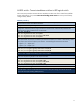
1. Change switch 2 member ID from default 1 to 2.
[H3C]irf member 1 renumber 2
2. Before continuing with the following steps, reboot the switch to make all interface numbering changes
from 1/x/y to 2/x/y. This command is executed when the switch is not in system mode.
<H3C>reboot
After rebooting
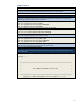
3. Shut down the IRF physical ports to prepare them to be included under the IRF logical port “irf-port 2/1”
configuration. Otherwise, when trying to include these interfaces later under IRF-Port, Comware will
indicate that the physical interfaces are not shut down.
[H3C]int ten2/0/27
[H3C-Ten-GigabitEthernet2/0/27]shut
[H3C-Ten-GigabitEthernet2/0/27]int ten2/0/28
[H3C-Ten-GigabitEthernet2/0/28]shut
4. Create Logical port “irf-port 2/1” and include ten2/0/27 and ten2/0/28.
[H3C]irf-port 2/1
[H3C-irf-port2/1]port group interface ten2/0/27
[H3C-irf-port2/1]port group interface ten2/0/28
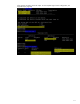
5. Unshut ten2/0/27 and ten2/0/28 to bring up the irf-link. After the links and interfaces appear, proceed
to the next step. Nothing happens until step 6 is executed.
[H3C]int ten2/0/27
[H3C-Ten-GigabitEthernet2/0/27]undo shut
[H3C-Ten-GigabitEthernet2/0/27]int ten2/0/28
[H3C-Ten-GigabitEthernet2/0/28]undo shut
6. Activate irf port configuration to start IRF peering between two switches. At this moment, nothing
happens because both switch 1 IRF physical links are still shut down.
[H3C]irf-port-configuration active
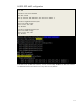
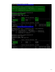
7. Go to Switch 1 (page 11) to start IRF physical links and activate the IRF-link configuration. Several
seconds later, switch 2 reloads itself with the message below (only part of the booting message is shown
here for reference).
IRF port 1 is up.
Starting......
************************************************************************
* *
* H3C S5800-32C BOOTROM, Version 205 *
* *
************************************************************************
Copyright (c) 2004-2010 Hangzhou H3C Technologies Co., Ltd.