
Virtual Connect and HP A-Series switches (A5820) IRF Integration Guide

5
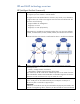
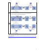
Network topology
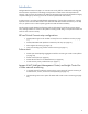
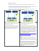
Physical diagram
The IRF cluster consists of one A5820 switch and one A5800-32C switch. Comware software
supports IRF clustering on different switch models if they are compatible with each other for IRF.
The A5820 and A5800 switches form an IRF bundle link between them with two 10G links. The
A5820 switch is switch 1, the master of the domain, and has logical port IRF-Port2. The A5800
switch is switch 2, the slave of the domain, and has logical port IRF-Port1, defined originally before
merging with the A5820 switch.
The A5820 and A5800 switches use one Gigabit Ethernet link as a BFD MAD link for MAD.
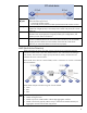
VC1 and VC2 are Flex-10 modules in interconnect bays 1 and 2 of the HP BladeSystem c7000
Enclosure. Each Flex-10 module has a SUS connecting to an IRF virtual device. A SUS consists of two
10G links terminated on A5820 and A5800 switches. With IRF, these two 10G links form one
bridge-aggregation bundle (the same as port channel on Cisco NX-OS and etherchannel on Cisco
IOS). VC1 connects the IRF cluster with the Bridge-Aggregation 2 interface, and VC2 connects the IRF
cluster with the Bridge-Aggregation 3 interface. Bridge-Aggregation 1 forms a virtual port channel