Technical whitepaper FCoE Cookbook for HP Virtual Connect Version 4.
Scenario 3: Dual-Hop FCoE using MultiFCoE networks and ports with Nexus 5xxx Series switch in FCF mode connected to Cisco MDS switches (using a SAN Port Channel) Benefits Considerations Requirements Guidelines Virtual Connect configuration Nexus configuration 37 38 38 39 39 40 40 Scenario 4: Multi-Hop FCoE using MultiFCoE networks and ports with Nexus 5xxx Series switch in FCF mode connected to a Cisco MDS switches (using a FCoE Port Channel) Benefits Considerations Requirements Guidelines Virtual Connect
Scenario 7: Dual-Hop FCoE using a single FCoE network and multiple ports with HP 5900 Series switch in FCF mode directly connected to an FCoE-Based storage target Benefits Considerations Requirements Guidelines Virtual Connect configuration HP 5900 configuration 84 84 85 85 86 86 86 Scenario 8: Dual-Hop FCoE using MultiFCoE networks and ports with HP FlexFabric 5900CP switch in NPV mode connected to Cisco MDS switches Benefits Considerations Requirements Guidelines Virtual Connect configuration HP 5900CP
QoS on Nexus 5010 and 5020 141 QoS on Nexus 5500 series 142 Quality of Service in the Virtual Connect Domain 144 Adding an FCoE volume in a multi-hop FCoE environment Identifying MAC and WWPN addresses of the FCoE adapter Configuring VFC interfaces Configuring the Storage Presentation Configuring the zoning Adding an FCoE volume to VMware ESX Adding an FCoE volume to Windows Server 2012 149 149 154 155 155 156 158 Virtual Connect Troubleshooting Troubleshooting DCBX issues Troubleshooting FCoE issues with
VMware vSphere not detecting FCoE adapters 210 Troubleshooting using server adapter management suite Emulex OneCommand Manager 211 211 FCoE Frames Analysis 213 Appendix A: FCoE Port Channel limitations on Nexus switches Identifying ports that belong to the same Nexus Unified Port Controller 216 216 Acronyms and abbreviations 218 FC/FCoE Port Types FCoE Port Types FC Port Types 220 220 220 Support and Other Resources Contacting HP Related documentation 221 221 222
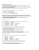
Purpose This guide provides concept, deployment guidelines and use case scenarios for HP Virtual Connect when using Fibre Channel over Ethernet through FIP Snooping under the T11 FC-BB-5 specification. Overview Fibre Channel over Ethernet (FCoE) through FIP Snooping under the T11 FC-BB-5 specification is supported on the HP Virtual connect modules since VC 4.
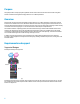
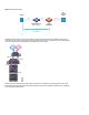
Figure 1: Dual Hop FCoE Design FC Storage Array Server FCoE FCoE Virtual Connect (FIP Snooping) Native FC FCoE Forwarder Dual-Hop FCoE Multi Hop FCoE technology can also be used to extend convergence beyond the external FCoE device. Multi Hop FCoE means there are more than two FCoE ‘hops’ between the server and the conversion point from FCoE to FC. This extended convergence design offers more flexibility and capital/operational cost savings.
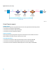
Figure 2: Multi Hop FCoE Design Server FCoE FCoE Virtual Connect (FIP Snooping) FCoE DCB Device Native FC FCoE Forwarder Multi-Hop FCoE Virtual Connect support VC Module support Extending FCoE through FIP Snooping with HP Virtual Connect is only supported with the following modules: HP Virtual Connect FlexFabric-20/40 F8 Module HP Virtual Connect FlexFabric 10Gb/24-port Module HP Virtual Connect Flex-10/10D Ethernet Module Firmware requirement FCoE through FIP Snooping using FC-BB-5 is supp
VC FlexFabric 10Gb/24-port X1 – X4 Uplink ports available for FCoE connection VC Flex-10/10D X1 – X10 Uplink ports available for FCoE connection VC FlexFabric-20/40 F8 X1 – X8 Uplink ports available for FCoE connection FcoE-enabled uplink port limitation Long Range Ethernet Optical transceivers (LR SFP+) are not supported on Virtual Connect FCoE-enabled uplink port. Server and enclosure limitations Double-dense server blade (i.e.
Upstream Switch support Supported upstream switch models you can connect to the VC modules are listed in the Virtual Connectivity stream documents available on the following HP’s SPOCK web page: http://h20272.www2.hp.com/Pages/spock2Html.aspx?htmlFile=hw_virtual_connect.html&lang=en&cc=us&hpapp id=hppcf in the Virtual Connect FCoE Modules section. (Requires HP Passport; if you do not have an HP Passport account, follow the instructions on the webpage).
This HP’S SPOCK document provides detailed information on recommended Firmware versions, supported upstream FC/FCoE switches, supported Virtual Connect modules, transceivers, Storage System, etc. HP 5900AF support The following describes the different scenarios currently supported by HP with HP 5900AF: VC<------>5900AF NPV/FCF<------>FCoE target VC<------>5900AF NPV<------>Nexus 5k FCoE<------>FC or FCoE target Variants of the above with more FCoE hops are supported up to the Cisco hop limit.
Virtual Connect Restrictions The following restrictions apply to VC modules and switches from different vendors: Up to 32 FCoE networks can be associated with any single set of uplink ports using the Multi-FCoE Network per Uplink Set support in VC 4.20 or later. With multi-FCoE Network per Uplink Set support, customers can benefit from Virtual SANs (VSANs) support but can also have the ability to provide connectivity to multiple types of SAN from the same Virtual Connect set of ports.
For each FCoE VLAN, a unique FC VSAN must be created on the switch and association between the two must be strictly configured as 1-to-1 (i. e. VLAN x maps with VSAN y and to increase the FCoE traffic identification, we recommend to use x=y, e.g. VLAN 200 maps with VSAN 200).
Virtual Connect requires the creation of an Active/Active Shared Uplink Set configuration for the FCoE traffic.
FCoE-capable Shared Uplink Sets must always be connected to a single Top of Rack switch in order to maintain the SAN-A / SAN-B isolation.
FCoE traffic is not allowed to cross stacking links. In a Multiple Enclosure VC Domain, VCM automatically reserves all same uplink ports on each VC module when creating a SUS that contains associated FCoE networks.
Scenario 1: Dual-Hop FCoE using a single FCoE network and port with Nexus 5xxx Series switch in FCF mode directly connected to FC/FCoE-Based storage targets In this scenario, two Converged Shared Uplink Sets using a single uplink port and carrying a single FCoE network and multiple standard Ethernet networks are created between the Virtual Connect modules and the Nexus switches. Each Nexus switch is directly connected to a FC or FCoE-based storage target.
Considerations In this scenario, the Nexus switches must operate as Fiber Channel Forwarders (FCF). This is the default Cisco Nexus 5xxx Series switches mode, it’s also called the fabric mode. In this mode, the switch provides standard Fibre Channel switching capability and features.
Requirements Refer to SPOCK C-Series FCoE Switch Connectivity stream at http://h20272.www2.hp.com/Pages/spock2Html.aspx?htmlFile=hw_switches.html for information on: Minimum NX-OS version Minimum Virtual Connect firmware version HP FlexFabric Adapter Firmware and driver Note: FCoE requires the Nexus Storage Protocols Services license (FC_FEATURES_PKG). This license is an option which is activated when the Nexus switch is shipped from Cisco.
Figure 12: Physical diagram EVA Storage Array FCoE WWN: 50:01:43:80:02:5D:19:72 3PAR Storage Array FC WWN: 50:01:43:80:02:5D:19:74 VSAN 200 WWN: 21:53:00:02:ac:00:15:9d VSAN 201 WWN: 20:53:00:02:ac:00:15:9d VSAN 200 Native Ethernet + Native Fibre Channel VSAN 201 LAN vfc 2007 vfc 2007 VLAN 200 eth1/1 Switch A Nexus-5010 FCF Mode VLAN 1,10,20 eth1/17 eth1/5 vfc 2005 vfc 2006 VLAN 201 eth1/1 fc2/1 eth1/5 vfc 2005 vfc 2006 fc2/1-2 FCoE VLAN 200 VLAN 1,10,20 VSAN 200 FCoE VLAN 201 VLAN 1,10,
Nexus switch-A configuration Upgrade the Nexus switch with minimum NX-OS supported version. Note: Refer to SPOCK C-Series FCoE Switch Connectivity stream for additional information at http://h20272.www2.hp.com/Pages/spock2Html.aspx?htmlFile=hw_switches.html Enable FCoE on the switch (disabled by default): o configure terminal o feature fcoe Note: The Nexus can require a reload.
Note: The MAC Address of the FCoE adapter is found under the Virtual Connect Server Profile: Create a virtual Fibre Channel interface for the second Blade server and bind it to the MAC address of its FCoE adapter 1: o interface vfc2006 o description vfc for server-2 o bind mac-address 00:17:a4:77:b8:dc o no shutdown Create a virtual Fibre Channel interface for the FCoE-based storage target and bind it to eth1/1: o o o o interface vfc2007 description vfc for EVA bind interface eth1/1 no shutdown # As
o o o o o interface Ethernet1/1 description FCoE uplink to EVA switchport mode trunk switchport trunk allowed vlan 200 spanning-tree port type edge trunk Configure the Fiber Channel interface connected to the 3PAR array: o interface fc 2/1 o switchport description Connected to the 3PAR array o no shutdown # Assign it to VSAN200 as a trunk port o switchport trunk allowed vsan 200 Assign the Virtual Fibre Channel interfaces (vfc) and the Fiber Channel interface to the FCoE VSAN: o o o o o o vsan datab
Configure the interface connected to the datacenter LAN: o interface eth 1/17 o switchport mode trunk o switchport trunk allowed vlan 1,10,20 Configuration of the zone: a. Create the first VSAN zone for the 3PAR Storage target: o zone name fcoe-zone-3PAR vsan 200 o member pwwn 21:53:00:02:ac:00:15:9d {This is the WWN of the first 3PAR controller port} o member pwwn 50:06:0b:00:00:c3:1a:20 {This is the WWN of the first Blade FlexFabric Adapter port 1} b.
Create a virtual Fibre Channel interface for the first Blade server and bind it to the MAC address of its FCoE adapter 2: o o o o interface vfc 2005 description vfc for server-1 bind mac-address 00:17:a4:77:b8:89 no shutdown Note: The MAC Address of the FCoE adapter is found under the Virtual Connect Server Profile: Create a virtual Fibre Channel interface for the second Blade server and bind it to the MAC address of its FCoE adapter 2: o interface vfc2006 o description vfc for server-2 o bind mac-ad
Create a trunk between the Nexus and the VC module Bay 2 with eth1/5 to pass the FCoE (VLAN 201) and Ethernet traffic (VLAN 1,10,20): o interface Ethernet1/5 o description FCoE uplink to VC-Bay2-X3 o switchport mode trunk o switchport trunk allowed vlan 1,10,20,201 o spanning-tree port type edge trunk Create a trunk on the interface connected to the FCoE-based storage device to pass the FCoE traffic (VLAN 201): o o o o o interface Ethernet1/1 description FCoE uplink to EVA switchport mode trunk switch
o member pwwn 50:06:0b:00:00:c3:1a:26 {This is the WWN of the second Blade FlexFabric Adapter port 2} e. Create zoneset: o zoneset name zoneset-EVA vsan 201 o member fcoe-zone-EVA f.
Scenario 2: Dual-Hop FCoE using a single FCoE network and port with Nexus 5xxx Series switch in FCF mode connected to Cisco MDS SAN switches (using a SAN Port Channel) In this scenario, two Converged Shared Uplink Sets using a single uplink port and carrying a single FCoE network and multiple standard Ethernet networks are created between the Virtual Connect modules and the Nexus switches. Each Nexus switch is connected to a Cisco MDS SAN Fabric through a SAN Port Channel.
Considerations The Nexus switches operate as Fiber Channel Forwarders (FCF). This is the default Cisco Nexus 5xxx Series switches mode, it’s also called the fabric mode. In this mode, the switch provides standard Fibre Channel switching capability and features. In a fully populated c7000 enclosure, the server-to-uplink ratio is 16:1. This configuration can result in poor response time and sometimes requires particular performance monitoring attention.
This cookbook provides only basic Cisco guidelines and configuration steps, for a more complete and detailed list of Nexus FCoE configuration guidelines, refer to the Fibre Channel over Ethernet Configuration Guides available at http://www.cisco.com/c/en/us/support/switches/nexus-5000-series-switches/products-installation-andconfiguration-guides-list.
Nexus configuration Details about the configuration: FCF mode is used. Interfaces eth1/5 are connected to the VC modules. Interfaces eth1/17 are connected to the datacenter LAN. Interfaces fc2/1 and fc2/2 are directly connected to Cisco MDS 9148 switches through a SAN Port Channel. SAN port channels spo100 are configured to pass FCoE VSANs 200 and 201. VLAN IDs 200 and 201 are used for the FCoE networks. VLAN IDs 1, 10 and 20 are the standard Ethernet networks (non-FCoE networks).
Nexus switch-A configuration Upgrade the Nexus switch with minimum NX-OS supported version. Note: Refer to SPOCK C-Series FCoE Switch Connectivity stream for additional information at http://h20272.www2.hp.com/Pages/spock2Html.aspx?htmlFile=hw_switches.html Enable FCoE on the switch (disabled by default): o configure terminal o feature fcoe Note: The Nexus can require a reload.
Create a virtual Fibre Channel interface for the second Blade server and bind it to the MAC address of its FCoE adapter 1: o interface vfc2006 o switchport description vfc for server-2 o bind mac-address 00:17:a4:77:b8:dc o no shutdown Create the VLANs for the IP traffic: o vlan 1,10,20 Create a trunk between the Nexus and the VC module Bay 1 with eth1/5 to pass the FCoE (VLAN 200) and Ethernet traffic (VLAN 1,10,20): o interface Ethernet1/5 o description FCoE uplink to VC-Bay1-X3 o switchport mode
Configuration of the zone: a. Create zones: o zone name fcoe-zone-3PAR vsan 200 o member pwwn 21:53:00:02:ac:00:15:9d {This is the WWN of the first 3PAR controller port} o member pwwn 50:06:0b:00:00:c3:1a:20 {This is the WWN of the first Blade FlexFabric Adapter port 1} o member pwwn 50:06:0b:00:00:c3:1a:24 {This is the WWN of the second Blade FlexFabric Adapter port 1} b.
Note: The MAC Address of the FCoE adapter is found under the Virtual Connect Server Profile: Create a virtual Fibre Channel interface for the second Blade server and bind it to the MAC address of its FCoE adapter 2: o interface vfc2006 o switchport description vfc for server-2 o bind mac-address 00:17:a4:77:b8:de o no shutdown Create the VLANs for the IP traffic: o vlan 1,10,20 Create a trunk between the Nexus and the VC module Bay 2 with eth1/5 to pass the FCoE (VLAN 201) and Ethernet traffic (VLA
Note: It is also necessary to configure port channeling on the MDS-B switch.
Scenario 3: Dual-Hop FCoE using Multi-FCoE networks and ports with Nexus 5xxx Series switch in FCF mode connected to Cisco MDS switches (using a SAN Port Channel) In this scenario, two Converged Shared Uplink Sets using multiple uplinks and carrying multiple FCoE networks and multiple standard Ethernet networks are created between the Virtual Connect modules and the Nexus switches. Each Nexus switch is connected to a Cisco MDS SAN Fabric through a trunk SAN Port Channel.
Benefits This configuration offers increased performance and better availability. The server-to-uplink ratio is adjustable, with the current NX software limitations, up to 2:1 with the Nexus 5500 series and VC Flex-10/10D (as few as two servers share one physical Fabric uplink) and up to 4:1 with the Nexus 5000 series. Using multiple FCoE uplink ports on each VC module connected to Nexus allows dynamically distribution of the FCoE traffic across the ports using a round robin format.
Figure 17: Cisco Nexus 5xxx switches operating as FC Forwarder (FCF) FC Storage Array A Server 1 (ENode) FCoE VLAN A VN_Port Server 2 N_Port Native FC VSAN A Lossless Ethernet network (ENode) F_Port Port Channel FCoE VLAN B VN_Port FCF VF_Ports Virtual Connect (FIP Snooping mode) SAN Port Channel and Trunking Native FC VSAN B F_Port TE_Ports Nexus 5xxx Series N_Port TE_Ports EISL FC Storage Array B Cisco MDS (FCF Mode) Dual-Hop FCoE Converged Ethernet/FCoE FC This cookbook provides
To increase the FCoE traffic identification and to better control the span of this traffic over the Ethernet network, it is recommended to use different FCoE VLANs and VSANs numbers between the two fabrics. FCoE VLANs should be dedicated to FCoE traffic (i.e. they should not carry IP traffic). FCoE VLAN cannot be configured as a native VLAN (the VLAN that carries untagged traffic on trunk ports, by default VLAN 1). Interfaces connecting to VC must be configured as trunk ports and STP edge ports.
Figure 18: Physical diagram 3PAR WWN: 21:53:00:02:ac:00:15:9d EVA WWN: 20:53:00:02:ac:00:15:9d VSAN 201 WWN: WWN: 50:01:43:80:02:5D:19:7C 50:01:43:80:02:5D:19:79 VSAN 300 VSAN 200 Cisco MDS-A 9148 VSAN 301 SAN-A fc1/9 LAN VSAN Trunk spo100 fc1/10 fc1/9 VSAN 200 VSAN 300 VSAN 201 VSAN 301 VLAN 1,10,20 eth1/17 Switch A Nexus-5010 FCF Mode fc1/10 VSAN Trunk spo100 VLAN 1,10,20 eth1/17 eth1/5-6 vfc 2005 vfc 2006 eth1/5-6 vfc 2005 vfc 2006 fc2/1-2 po200 FCoE VLAN 200, 300 VLAN 1,10,20 VSA
Nexus switch-A configuration Upgrade the Nexus switch with minimum NX-OS supported version. Note: Refer to SPOCK C-Series FCoE Switch Connectivity stream for additional information at http://h20272.www2.hp.com/Pages/spock2Html.aspx?htmlFile=hw_switches.html Enable FCoE and LACP on the switch (disabled by default): o configure terminal o feature fcoe o feature lacp Note: The Nexus can require a reload.
Create a virtual Fibre Channel interface for the second Blade server and bind it to the MAC address of its FCoE adapter 1: o interface vfc2006 o description vfc for server-2 o bind mac-address 00:17:a4:77:b8:dc o no shutdown Create a SAN port channel with VSAN Trunking allowing the two FCoE VSANs (200 and 300) between the Nexus and MDS-A switch using the two fiber channel interfaces: o interface san-port-channel 100 o switchport description SAN-Trunk-Port-Channel to MDS-A o channel mode active o switch
switchport trunk allowed vsan add 300 interface fc1/9-10 switchport description Connected to Nexus-A-fc2/1-2 channel-group 100 no shutdown vsan database vsan 200 vsan 200 interface port-channel 100 Assign the Virtual Fibre Channel interfaces (vfc) and the SAN Port Channel to the FCoE VSANs: o o o o o o vsan database vsan 200 vsan 200 interface san-port-channel 100 vsan 200 interface vfc 2005 vsan 300 vsan 300 interface vfc 2006 Configure the interface connected to the d
Nexus switch-B configuration Upgrade the Nexus switch with minimum NX-OS supported version. Note: Refer to SPOCK C-Series FCoE Switch Connectivity stream for additional information at http://h20272.www2.hp.com/Pages/spock2Html.aspx?htmlFile=hw_switches.html Enable FCoE and LACP on the switch (disabled by default): o configure terminal o feature fcoe o feature lacp Note: The Nexus can require a reload.
Note: The MAC Address of the FCoE adapter is found under the Virtual Connect Server Profile: Create a virtual Fibre Channel interface for the second Blade server and bind it to the MAC address of its FCoE adapter 2: o interface vfc2006 o description vfc for server-2 o bind mac-address 00:17:a4:77:b8:de o no shutdown Create a SAN port channel with VSAN Trunking allowing the two FCoE VSANs (201 and 301) between the Nexus and MDS-B switch using the two fiber channel interfaces: o interface san-port-chann
switchport trunk allowed vsan add 301 interface fc1/9-10 switchport description Connected to Nexus-B-fc2/1-2 channel-group 100 no shutdown Assign the Virtual Fibre Channel interfaces (vfc) and the SAN Port Channel to the FCoE VSANs: o o o o o o vsan database vsan 201 vsan 201 interface san-port-channel 100 vsan 201 interface vfc 2005 vsan 301 vsan 301 interface vfc 2006 Configure the interface connected to the datacenter LAN: o interface eth 1/17 o switchport mode trunk o switchpor
Scenario 4: Multi-Hop FCoE using Multi-FCoE networks and ports with Nexus 5xxx Series switch in FCF mode connected to a Cisco MDS switches (using a FCoE Port Channel) In this Multi-hop FCoE scenario, two Converged Shared Uplink Sets using multiple uplinks and carrying multiple FCoE networks and multiple standard Ethernet networks are created between the Virtual Connect modules and the Nexus switches and each Nexus switch is connected to a Cisco MDS SAN Fabric through a trunk FCoE Port Channel.
Benefits This Multi-Hop FCoE scenario extends convergence beyond the Top of Rack switches but at the same time it preserves all your Fibre Channel SAN switch investments. Extended convergence offers more flexibility and capital/operational cost savings. Nexus 50xx switches have a limited number of 8Gb FC port (5010=6 max, 5020=12 max) so this scenario can help customers running out of Fibre Channel ports on Nexus 50xx switches by using FCoE links instead of FC to reach the MDS SAN switches.
Figure 20: Cisco Nexus 5xxx switches operating as FC Forwarder (FCF) FC Storage Array A Server 1 (ENode) FCoE VLAN A VN_Port FCoE storage N_Port FC storage Native FC Lossless Ethernet network VSAN A Server 2 F_Port (ENode) Port Channel Port Channel FCoE VLAN B VN_Port VF_Ports VE_Ports F_Port VSAN B N_Port VE_Ports FC Storage Array B Native FC Virtual Connect (FIP Snooping mode) Nexus 5xxx Series Cisco MDS (FCF Mode) Multi-Hop FCoE Converged Ethernet/FCoE FC FCoE This cookbook p
To reduce the risk of congestion, it is recommended to use FCoE Port Channeling. To increase the FCoE traffic identification and to better control the span of this traffic over the Ethernet network, it is recommended to use different FCoE VLANs and VSANs numbers between the two fabrics. FCoE VLANs should be dedicated to FCoE traffic (i.e. they should not carry IP traffic). FCoE VLAN cannot be configured as a native VLAN (the VLAN that carries untagged traffic on trunk ports, by default VLAN 1).
Interfaces fc1/1 are connected to the EVA and fc1/2 are connected to the 3PAR. The EVA is connected to VSAN 30x and the 3PAR is connected to VSANs 20x.
Nexus switch-A configuration Upgrade the Nexus switch with minimum NX-OS supported version. Note: Refer to SPOCK C-Series FCoE Switch Connectivity stream for additional information at http://h20272.www2.hp.com/Pages/spock2Html.aspx?htmlFile=hw_switches.html Enable FCoE and LACP on the switch (disabled by default): o configure terminal o feature fcoe o feature lacp Note: The Nexus can require a reload.
Note: The MAC Address of the FCoE adapter is found under the Virtual Connect Server Profile: Create a virtual Fibre Channel interface for the second Blade server and bind it to the MAC address of its FCoE adapter 1: o interface vfc2006 o description vfc for server-2 o bind mac-address 00:17:a4:77:b8:dc o no shutdown Create a port channel between the Nexus switch A and the MDS-A switch with eth1/19 and eth1/20. eth1/19 and eth1/20 can be used because both are mapped to the same UPC (i.e.
o switchport trunk allowed vsan 200 o switchport trunk allowed vsan add 300 o no shutdown Assign the Virtual Fibre Channel interfaces (vfc) and the Port Channel to the FCoE VSANs: o o o o o o vsan database vsan 200 vsan 200 interface vfc 2005 vsan 200 interface vfc 1000 vsan 300 vsan 300 interface vfc 2006 Configure the interface connected to the datacenter LAN: o interface eth 1/17 o switchport mode trunk o switchport trunk allowed vlan 1,10,20 Configuration of the zone: a.
MDS 9506 switch-A configuration Upgrade the MDS switch with minimum system version MDS NX-OS 5.2(6a) or with NX-OS 6.2(3) if you use Broadcom FlexFabric adapters. Note: A minimum version is required as the Cisco MDS 9000 10-Gbps 8-Port FCoE Module is only supported with MDS NX-OS 5.2(6a) or later. Note: With 534FLR-SFP+, 534FLB, 534M adapters, the Cisco MDS 9000 10-Gbps 8-Port FCoE Module is only supported with NX-OS 6.2(3).
o o o o o switchport description Connected to EVA no shutdown interface fc1/2 switchport description Connected to 3PAR no shutdown Assign the Virtual Fibre Channel interfaces (vfc) and the Fibre Channel interfaces (fc) to the FCoE VSANs: o o o o o o o o vsan database vsan 200 vsan 200 name 3PAR-VSAN vsan 200 interface vfc 1000 vsan 200 interface fc1/1 vsan 300 vsan 300 name EVA-VSAN vsan 301 interface fc1/2 Configuration of the zone: a.
Nexus switch-B configuration Upgrade the Nexus switch with minimum NX-OS supported version. Note: Refer to SPOCK C-Series FCoE Switch Connectivity stream for additional information at http://h20272.www2.hp.com/Pages/spock2Html.aspx?htmlFile=hw_switches.html Enable FCoE and LACP on the switch (disabled by default): o configure terminal o feature fcoe o feature lacp Note: The Nexus can require a reload.
Note: The MAC Address of the FCoE adapter is found under the Virtual Connect Server Profile: Create a virtual Fibre Channel interface for the second Blade server and bind it to the MAC address of its FCoE adapter 2: o interface vfc2006 o description vfc for server-2 o bind mac-address 00:17:a4:77:b8:de o no shutdown Create a port channel between the Nexus switch B and the MDS-B switch with eth1/19 and eth1/20. eth1/19 and eth1/20 can be used because both are mapped to the same UPC (i.e.
o no shutdown Assign the Virtual Fibre Channel interfaces (vfc) and the SAN Port Channel to the FCoE VSANs: o o o o o o vsan database vsan 201 vsan 201 interface vfc 2005 vsan 201 interface vfc 1000 vsan 301 vsan 301 interface vfc 2006 Configure the interface connected to the datacenter LAN: o interface eth 1/17 o switchport mode trunk o switchport trunk allowed vlan 1,10,20 Configuration of the zone: a.
Enable FCoE and LACP on the switch (disabled by default): o o o o configure terminal install feature-set fcoe feature-set fcoe feature lacp Associate each VLAN with a VSAN for each FCoE networks: o o o o vlan 201 fcoe vsan 201 vlan 301 fcoe vsan 301 Note: Enabling FCoE on VLAN 1 is not supported.
o o o o vsan 201 interface fc1/1 vsan 301 vsan 301 name EVA-VSAN vsan 301 interface fc1/2 Configuration of the zone: a. Create the first VSAN zone for the 3PAR Storage target: o zone name fcoe-zone-3PAR vsan 201 o member pwwn 20:53:00:02:ac:00:15:9d {This is the WWN of the second 3PAR controller port} o member pwwn 50:06:0b:00:00:c3:1a:22 {This is the WWN of the first Blade FlexFabric Adapter port 2} b. Create zoneset: o zoneset name zoneset-3PAR vsan 201 o member fcoe-zone-3PAR c.
Scenario 5: Dual-Hop FCoE using Multi-FCoE networks and ports with Nexus 5xxx Series switch in NPV mode connected to Brocade SAN switches. In this scenario, the Nexus switches operate as FCoE Gateways. This particular mode of operation is enabled by using the Nexus NPV mode.
Benefits This scenario can be used to simplify third-party interoperability concerns in environment where different types of Fibre Channel switches are used (i.e. when connecting Nexus 5xxx to a non-Cisco Fibre Channel switch like a Brocade SAN switch) because in NPV mode, the switch does not participate in domain operations or perform local switching. This enables multivendor topologies to be implemented without the restrictions the FCF mode requires.
Figure 23: Cisco Nexus 5xxx switches operating as an NPV Gateway Server Lossless Ethernet network (ENode) FCoE Gateway Native FC Port Channel NP_Ports N_Port NPIV VN_Port VF_Ports Virtual Connect (FIP Snooping mode) F_Ports F_Port Nexus 5xxx Series Brocade SAN Switch (NPV Mode) (NPIV Enabled) Dual-Hop FCoE FC Storage Array Converged Ethernet/FCoE FC This cookbook provides only basic Cisco guidelines and configuration steps, for a more complete and detailed list of Nexus FCoE configurat
FCoE VLAN cannot be configured as a native VLAN (the VLAN that carries untagged traffic on trunk ports, by default VLAN 1). Interfaces connecting to VC must be configured as trunk ports and STP edge ports. For each Blade server, one vfc interface with MAC Binding must be defined because Virtual Connect is running in FIP snooping mode. NPIV support is required in FC switches that connect to the Nexus NP Ports.
Interfaces fc2/1 and fc2/2 are connected to Brocade Core switches using NPIV (NP_Ports). Interface fc2/1 is mapped to VSAN 200/201 and fc2/2 to VSAN 300/301 (Alternativelly, you can assign both interfaces to all VSANs). VLAN IDs 200, 300, 201 and 301 are used for the FCoE networks. VLAN 200 maps to VSAN 200, VLAN 300 to VSAN 300, VLAN 201 to VSAN 201 and VLAN 301 to VSAN 301 VLAN IDs 1, 10 and 20 are the standard Ethernet networks (non-FCoE networks).
Nexus switch-A configuration Upgrade the Nexus switch with minimum NX-OS supported version. Note: Refer to SPOCK C-Series FCoE Switch Connectivity stream for additional information at http://h20272.www2.hp.com/Pages/spock2Html.aspx?htmlFile=hw_switches.html Enable NPV: o configure terminal o feature npv Note: Switching to NPV mode automatically performs a configuration erase and reloads the switch.
o channel-group 200 mode active o lacp rate fast Create the VLANs for the IP traffic: o vlan 1,10,20 Create a trunk on the port channel interface to pass the FCoE VLANs 200 and 300 and Ethernet traffic (VLAN 1,10,20): o o o o o interface port-channel 200 description FCoE Port Channel to VC-Bay1-X3/X4 switchport mode trunk switchport trunk allowed vlan 1,10,20,200,300 spanning-tree port type edge trunk Create a virtual Fibre Channel interface for the first Blade server and bind it to the MAC addres
Create a virtual Fibre Channel interface for the second Blade server and bind it to the MAC address of its FCoE adapter: o o o o interface vfc2006 description vfc for server-2 bind mac-address 00:17:a4:77:b8:a8 no shutdown Assign the Fibre Channel interfaces and the Virtual Fibre Channel interfaces (vfc) to the appropriate FCoE VSANs: o vsan database o vsan 200 o vsan 200 interface fc2/1 o vsan 200 interface vfc 2005 o vsan 300 o vsan 300 interface fc2/2 o vsan 300 interface vfc 2006 Note: Alternative
Configure the Fibre Channel interfaces connected to the Brocade-B SAN switch: o o o o interface fc 2/1 switchport description NP Port connected to Brocade-B switchport mode np no shutdown Note: The upstream Brocade SAN switch needs to be NPIV-enabled.
Note: The MAC Address of the FCoE adapter is found under the Virtual Connect Server Profile: Create a virtual Fibre Channel interface for the second Blade server and bind it to the MAC address of its FCoE adapter: o o o o interface vfc2006 description vfc for server-2 bind mac-address 00:17:a4:77:b8:a9 no shutdown Assign the Fibre Channel interfaces and the Virtual Fibre Channel interfaces (vfc) to the appropriate FCoE VSANs: o o o o o o o vsan database vsan 201 vsan 201 interface fc2/1 vsan 201 int
Scenario 6: Dual-Hop FCoE using Multi-FCoE networks and ports with Nexus 5xxx Series switch in NPV mode connected to Cisco MDS switches (using a SAN Port Channel) In this scenario, the Nexus switches operate as FCoE Gateways. This particular mode of operation is enabled by using the Nexus NPV mode.
Benefits Although the NPV mode can be intended to help address third-party interoperability issues in multivendor environment, in large Cisco fabrics, the NPV mode can be used to simplify the switch configuration, the points of management and also to better control the number of domain IDs to increase the SAN scalability as you can add switches to the faric without adding more domain IDs but the number of ports to the fabric are increased.
Figure 26: Cisco Nexus 5xxx switches operating as an NPV Gateway FC Storage Array A Server 1 (ENode) FCoE VLAN A VN_Port Server 2 N_Port VSAN A Lossless Ethernet network Native FC SAN Port Channel with Trunking (ENode) Port Channel FCoE VLAN B F_Port VSAN B F_Port NPIV VN_Port VF_Ports Virtual Connect (FIP Snooping mode) TNP_Ports Nexus 5xxx Series (NPV Mode) Dual-Hop FCoE FCoE Gateway N_Port TF_Ports FC Storage Array B Cisco MDS (NPIV Enabled) Converged Ethernet/FCoE FC This cookb
To increase the FCoE traffic identification and to better control the span of this traffic over the Ethernet network, it is recommended to use different FCoE VLANs and VSANs numbers between the two fabrics. FCoE VLANs should be dedicated to FCoE traffic (i.e. it should not carry IP traffic). FCoE VLAN cannot be configured as a native VLAN (the VLAN that carries untagged traffic on trunk ports, by default VLAN 1). Interfaces connecting to VC must be configured as trunk ports and STP edge ports.
Figure 27: Physical diagram 3PAR WWN: 21:53:00:02:ac:00:15:9d EVA WWN: 20:53:00:02:ac:00:15:9d VSAN 201 WWN: WWN: 50:01:43:80:02:5D:19:7C 50:01:43:80:02:5D:19:79 VSAN 300 VSAN 200 Cisco MDS-A 9148 LAN VSAN 301 SAN-A fc1/9 fc1/10 VSAN Trunk spo100 fc1/9 VSAN 200 VSAN 300 VSAN 201 VSAN 301 VLAN 1,10,20 eth1/17 Switch A Nexus-5010 NPV Mode fc1/10 VSAN Trunk spo100 VLAN 1,10,20 eth1/17 eth1/5-6 vfc 2005 vfc 2006 eth1/5-6 vfc 2005 vfc 2006 fc2/1-2 po200 FCoE VLAN 200, 300 VLAN 1,10,20 VSAN
Nexus switch-A configuration Upgrade the Nexus switch with minimum NX-OS supported version. Note: Refer to SPOCK C-Series FCoE Switch Connectivity stream for additional information at http://h20272.www2.hp.com/Pages/spock2Html.aspx?htmlFile=hw_switches.html Enable NPV: o configure terminal o feature npv Note: Switching to NPV mode automatically performs a configuration erase and reloads the switch.
o o o o interface vfc 2005 description vfc for server-1 bind mac-address 00:17:a4:77:b8:88 no shutdown Note: The MAC Address of the FCoE adapter is found under the Virtual Connect Server Profile: Create a virtual Fibre Channel interface for the second Blade server and bind it to the MAC address of its FCoE adapter 1: o interface vfc2006 o description vfc for server-2 o bind mac-address 00:17:a4:77:b8:dc o no shutdown Create a SAN port channel with VSAN Trunking allowing the two FCoE VSANs (200 and 3
To enable NPIV use feature npiv.
Associate each VLAN with a VSAN for each FCoE networks: o o o o vlan 201 fcoe vsan 201 vlan 301 fcoe vsan 301 Note: Enabling FCoE on VLAN 1 is not supported. Note: Make sure that these VLAN IDs are the same as the second Shared Uplink Set FCoE’s VLAN IDs in VCM.
Note: The MAC Address of the FCoE adapter is found under the Virtual Connect Server Profile: Create a virtual Fibre Channel interface for the second Blade server and bind it to the MAC address of its FCoE adapter 2: o interface vfc2006 o description vfc for server-2 o bind mac-address 00:17:a4:77:b8:de o no shutdown Create a SAN port channel with VSAN Trunking allowing the two FCoE VSANs (201 and 301) between the Nexus and MDS-B switch using the two fiber channel interfaces: o interface san-port-chann
switchport trunk allowed vsan 201 switchport trunk allowed vsan add 301 interface fc1/9-10 switchport description Connected to Nexus-B-fc2/1-2 channel-group 100 no shutdown Assign the Virtual Fibre Channel interfaces (vfc) and the SAN Port Channel to the FCoE VSANs: o o o o o o vsan database vsan 201 vsan 201 interface san-port-channel 100 vsan 201 interface vfc 2005 vsan 301 vsan 301 interface vfc 2006 Configure the interface connected to the datacenter LAN: o interface eth 1/
Scenario 7: Dual-Hop FCoE using a single FCoE network and multiple ports with HP 5900 Series switch in FCF mode directly connected to an FCoE-Based storage target In this scenario, two Converged Shared Uplink Sets using a single or multiple uplink ports and carrying a single FCoE network and multiple standard Ethernet networks are created between the Virtual Connect modules and the HP 5900AF or HP FlexFabric 5900CP switches. Each HP 5900 switch is directly connected to an FCoE-based storage target.
Considerations In this scenario, the HP 5900 switches must operate as Fiber Channel Forwarders (FCF). In this mode, the switch provides standard Fibre Channel switching capability and features including expansion, fabric, trunk VF and N ports, and aggregation of E-port and N-port virtualization; fabric services such as name server, registered state change notification, and login services; per-VSAN fabric services, FSPF, soft and hard zoning, Fibre Channel traceroute, ping, debugging, and FIP snooping.
Minimum HP Comware Software version Virtual Connect firmware version HP FlexFabric Adapter Firmware and driver Note: License is not required for FCoE on HP 5900 switches. Guidelines It is mandatory to use the FCF Mode in order to directly attach FCoE-based Storage devices. To increase the FCoE traffic identification and to better control the span of this traffic over the Ethernet network, it is recommended to use different FCoE VLANs and VSANs numbers between the two fabrics.
Figure 30: Physical diagram 3PAR Storage Array WWN: 20:81:00:02:ac:00:15:9d WWN: 21:81:00:02:ac:00:15:9d Switch A HP 5900 FCF Mode Native Ethernet + FCoE / DCB FCoE FCoE vfc 7 XGE1/0/7 FCoE VLAN 200 LAN vfc 7 XGE1/0/7 FCoE VLAN 201 VLAN 1,10,20 XGE1/0/23 XGE1/0/12-14 VLAN 1,10,20 XGE1/0/23 Switch B HP 5900 FCF Mode XGE1/0/12-14 BAGG 20 vfc 1 vfc 2 FCoE VLAN 200 VLAN 1,10,20 VSAN 200 FCoE VLAN 201 VLAN 1,10,20 VSAN 201 X3 – X4 X3 – X4 BAGG 20 vfc 1 vfc 2 VC FlexFabric Bay 1 FCoE / DCB VC
HP 5900 switch-A configuration Upgrade the HP 5900 switch with minimum supported firmware version (to get the running version, enter: display version). Note: Refer to SPOCK connectivity stream documents for 5900 Series for additional information at http://h20272.www2.hp.com/Pages/spock2Html.aspx?htmlFile=hw_switches.
o import 7 export 0 Create VLANs: (by default VLAN 1 is already configured) o vlan 10 o vlan 20 Create a VSAN 200 for the FCoE traffic: o vsan 200 # Disable the fabric configuration function in VSAN 200 o undo domain configure enable # Configure the domain ID as 200 in VSAN 200 o domain-id 200 static # Configuration of a zone alias for the FCoE Nodes.
o qos apply policy DCBX outbound # For PFC: Configure the interface to automatically negotiate with its peer to enable PFC o priority-flow-control auto Enable PFC for 802.1p priority 3 on the interface o priority-flow-control no-drop dot1p 3 Configure the interface to trust the 802.
# Enable Spanning Port Fast o stp edged-port # For DCBX: Enable LLDP on the interface, and enable the interface to advertise DCBX TLVs o lldp enable o lldp tlv-enable dot1-tlv dcbx Apply the QoS policy named DCBX to the outgoing traffic o qos apply policy DCBX outbound # For PFC: Configure the interface to automatically negotiate with its peer to enable PFC o priority-flow-control auto Enable PFC for 802.
Note: The MAC Address of the FCoE adapter is found under the Virtual Connect Server Profile: Create a virtual Fibre Channel interface for the second Blade server o interface vfc 2 o description vfc for Server-2 # Bind it to the MAC address of the second Blade server FCoE adapter 1 o bind interface Ten-GigabitEthernet1/0/12 mac 0017-a477-bc46 # Assign it to the FCoE VSAN o port trunk vsan 200 Option 2: Configuration with a bridge aggregation between VC and 5900.
# For PFC: Configure the interface to automatically negotiate with its peer to enable PFC o priority-flow-control auto Enable PFC for 802.1p priority 3 on the interface o priority-flow-control no-drop dot1p 3 Configure the interface to trust the 802.
Create a virtual Fibre Channel interface for the second Blade server o interface vfc 2 o description vfc for Server-2 # Bind the Bridge Aggregation to the MAC address of the first Blade server FCoE adapter 1 o bind interface Bridge-Aggregation20 mac 0017-a477-bc46 # Assign it to the FCoE VSAN o port trunk vsan 200 HP 5900 switch-B configuration Upgrade the HP 5900 switch with minimum supported firmware version (to get the running version, enter: display version).
o lldp global enable. # Create Ethernet frame header ACL numbered 4000, and configure the ACL to permit FCoE packets (whose protocol number is 0x8906) and FIP packets (whose protocol number is 0x8914) to pass through. o acl number 4000 name DCBX o rule 0 permit type 8906 ffff o rule 1 permit type 8914 ffff # Create a class named DCBX, specify the operator of the class as OR, and use ACL 4000 as the match criterion of the class.
# Configuration of the zone for the 3PAR Array o zone name fcoe-zone-3PAR o member zone-alias FCoE-Nodes o member zone-alias FCoE-ports-3PAR # Configuration of the zoneset for the 5900 VSAN 201 o zoneset name vsan201-5900 o member fcoe-zone-3PAR o zoneset distribute full Enable FCoE for VLAN 201 and map it to VSAN 201 o vlan 201 o description FCoE-ToSAN-B o fcoe enable vsan 201 Note: Make sure that this VLAN ID is the same as the second Shared Uplink Set FCoE’s VLAN ID in VCM.
o qos wrr cs6 group sp o qos wrr cs7 group sp Create a virtual Fibre Channel interface for the 3PAR Array o interface vfc 7 o description vfc for 3PAR # Configure it to operate in F mode o fc mode f # Bind it to interface Ten-GigabitEthernet 1/0/7 (this is the Ethernet port that 3PAR StoreServ is connected to) o bind interface Te1/0/7 # Assign it to VSAN200 as a trunk port o port trunk vsan 201 Configure the interface connected to the datacenter LAN: o interface ten-gigabitethernet1/0/23 o description
Assign the other 50% to queue 0 (be) for standard LAN traffic. o qos wrr be group 1 byte-count 1 Assign all other queues to the SP group.
Option 2: Configuration with several uplinks between VC and 5900.
Create a virtual Fibre Channel interface for the first Blade server o interface vfc 1 o description vfc for Server-1 # Bind the Bridge Aggregation to the MAC address of the first Blade server FCoE adapter 2 o bind interface Bridge-Aggregation20 mac 0017-a477-bc39 # Assign it to the FCoE VSAN o port trunk vsan 201 Note: The MAC Address of the FCoE adapter is found under the Virtual Connect Server Profile: Create a virtual Fibre Channel interface for the second Blade server o interface vfc 2 o descriptio
Scenario 8: Dual-Hop FCoE using Multi-FCoE networks and ports with HP FlexFabric 5900CP switch in NPV mode connected to Cisco MDS switches In this scenario, the HP FlexFabric 5900CP switches operate as FCoE Gateways. This particular mode of operation is enabled by using NPV mode. In this scenario, two Converged Shared Uplink Sets using multiple uplink ports and carrying multiple FCoE networks and multiple standard Ethernet networks are created between the Virtual Connect modules and 5900CP switches.
Benefits This scenario can be used to simplify third-party interoperability concerns in environment where different types of Fibre Channel switches are used (i.e. when connecting HP5900 switches to a Cisco Fibre Channel switch like a MDS SAN switch) because in NPV mode, the switch does not participate in domain operations or perform local switching. This enables multivendor topologies to be implemented without the restrictions the FCF mode requires.
Figure 32: Dual-Hop FCoE with HP FlexFabric 5900CP-48XG-4QSFP+ Switch operating as an FCoE Gateway (NPV) Server Lossless Ethernet network FCoE Gateway Native FC (ENode) Port Channel NP_Ports N_Port NPIV VN_Port VF_Ports Virtual Connect HP 5900CP (FIP Snooping mode) (NPV Mode) F_Port F_Ports Cisco MDS SAN Switch FC Storage Array (NPIV Enabled) Dual-Hop FCoE Converged Ethernet/FCoE FC This cookbook provides only basic HP guidelines and configuration steps for the HP 5900 Switch Series, f
When a NP uplink fails, the disrupted server connections re-login on other NP uplink. Cisco SAN Port Channel (TNP Ports) are not supported with non Cisco SAN fabrics (i.e with HP 5900CP). When Multiple VSANs are used, there are 2 options: o If you want to assign servers to a specific FC interface: map one NP uplink to one VSAN. o If you don’t need to assign servers to any specific FC interfaces: map all NP uplinks to all VSANs.
Figure 33: Physical diagram EVA Storage Array FC WWN: 50:01:43:80:02:5D:19:72 WWN: 50:01:43:80:02:5D:19:74 VSAN 300 fc1/1 3PAR Storage Array FC WWN: 20:53:00:02:ac:00:15:9d WWN: 21:53:00:02:ac:00:15:9d VSAN 301 VSAN 200 fc1/2 fc1/1 Cisco MDS-A 9148 VSAN 201 fc1/2 Cisco MDS-B 9148 fc1/9 fc1/10 fc1/9 VSAN 200 VSAN 300 Native Ethernet + Native Fibre Channel fc1/10 VSAN 201 VSAN 301 LAN Switch A HP 5900CP NPV Mode VLAN 1,10,20 XGE1/0/15 VLAN 1,10,20 XGE1/0/15 FC1/0/35-36 XGE1/0/12-14
HP 5900 switch-A configuration Upgrade the HP 5900CP switch with minimum supported firmware version (to get the running version, enter: display version). Note: Refer to SPOCK HP FlexFabric 5900CP Ethernet/FCoE/FC Switch Connectivity stream for additional information at http://h20272.www2.hp.com/Pages/spock2Html.aspx?htmlFile=hw_switches.
o import 7 export 0 Create VLANs: (by default VLAN 1 is already configured) o vlan 10 o vlan 20 Create VSAN 200 and 300 for the FCoE traffic: o vsan 200 o vsan 300 Associate each VLAN with a VSAN for each FCoE network: o o o o o o vlan 200 description FCoE-To-3PAR fcoe enable vsan 200 vlan 300 description FCoE-To-EVA fcoe enable vsan 300 Note: Make sure that this VLAN ID is the same as the first Shared Uplink Set FCoE’s VLAN ID in VCM.
o priority-flow-control auto Enable PFC for 802.1p priority 3 on the interface o priority-flow-control no-drop dot1p 3 Configure the interface to trust the 802.1p priority carried in packets o qos trust dot1p # For ETS: Enable byte-count Weighted Round Robin o qos wrr byte-count Assign 50% of the interface bandwidth to queue 1 (af1) for FCoE traffic o qos wrr af1 group 1 byte-count 1 Assign the other 50% to queue 0 (be) for standard LAN traffic.
Note: The MAC Address of the FCoE adapter is found under the Virtual Connect Server Profile: Create a virtual Fibre Channel interface for the second Blade server o interface vfc 2 o description vfc for Server-2 # Bind the Bridge Aggregation to the MAC address of the first Blade server FCoE adapter 1 o bind interface Bridge-Aggregation20 mac 0017-a477-bc46 # Assign it to the FCoE EVA VSAN o port trunk vsan 200 MDS 9148 switch-A configuration Upgrade the MDS switch with minimum supported system version
Configuration of the Fibre Channel ports connected to the storage arrays: o o o o o o interface fc1/1 switchport description Connected to EVA no shutdown interface fc1/2 switchport description Connected to 3PAR no shutdown Assign the Fibre Channel interfaces (fc) to the FCoE VSANs: o o o o o o o o o vsan database vsan 200 vsan 200 name 3PAR-VSAN vsan 200 interface fc1/2 vsan 200 interface fc 1/9 vsan 200 interface fc1/10 vsan 300 vsan 300 name EVA-VSAN vsan 300 interface fc1/1 Configuration of the
o system-view o system-working-mode advance Note: The switch requires a reboot (enter: save, quit then reboot). Configure Switch B to operate in NPV mode: o system-view o fcoe-mode npv Configure DCBX: # Enable LLDP globally in case LLDP has been disabled (enabled by default): o lldp global enable. # Create Ethernet frame header ACL numbered 4000, and configure the ACL to permit FCoE packets (whose protocol number is 0x8906) and FIP packets (whose protocol number is 0x8914) to pass through.
o vsan 301 Associate each VLAN with a VSAN for each FCoE network: o o o o o o vlan 201 description FCoE-To-3PAR fcoe enable vsan 201 vlan 301 description FCoE-To-EVA fcoe enable vsan 301 Note: Make sure that this VLAN ID is the same as the second Shared Uplink Set FCoE’s VLAN ID in VCM.
Assign 50% of the interface bandwidth to queue 1 (af1) for FCoE traffic o qos wrr af1 group 1 byte-count 1 Assign the other 50% to queue 0 (be) for standard LAN traffic. o qos wrr be group 1 byte-count 1 Assign all other queues to the SP group.
Note: The MAC Address of the FCoE adapter is found under the Virtual Connect Server Profile: Create a virtual Fibre Channel interface for the second Blade server o interface vfc 2 o description vfc for Server-2 # Bind the Bridge Aggregation to the MAC address of the first Blade server FCoE adapter 2 o bind interface Bridge-Aggregation20 mac 0017-a477-bc47 # Assign it to the FCoE EVA VSAN o port trunk vsan 301 MDS 9148 switch-B configuration Upgrade the MDS switch with minimum supported system version
o o o o o o interface fc1/1 switchport description Connected to EVA no shutdown interface fc1/2 switchport description Connected to 3PAR no shutdown Assign the Fibre Channel interfaces (fc) to the FCoE VSANs: o o o o o o o o o vsan database vsan 201 vsan 201 name 3PAR-VSAN vsan 201 interface fc1/2 vsan 201 interface fc 1/9 vsan 201 interface fc1/10 vsan 301 vsan 301 name EVA-VSAN vsan 301 interface fc1/1 Configuration of the zone: g.
Scenario 9: Multi-Hop FCoE using Multi-FCoE networks and ports with HP 5900 Series switch in NPV mode connected to a Nexus 5xxx Series switches (using a FCoE Port Channel) In this Multi-hop FCoE scenario, two Converged Shared Uplink Sets using a single or multiple uplink ports and carrying a single FCoE network and multiple standard Ethernet networks are created between Virtual Connect modules and HP 5900 switches.
Using multiple FCoE uplink ports on each VC module connected to the HP 5900 and on each HP 5900 connected to the Nexus allow dynamically distribution of the FCoE traffic across the ports using a round robin format. FCoE Port Channeling increases the high availability and create enough FCoE SAN subscription. Considerations Enabling convergence in the extended network requires more careful bandwidth management than a Dual-Hop FCoE topology.
Figure 35: Multi-Hop FCoE with HP 5900AF switch operating as an FCoE Gateway (NPV) FCoE Storage Array A Server 1 (ENode) FCoE VLAN A VN_Port VN_Port Lossless Ethernet network VSAN A Server 2 VF_Port (ENode) Port Channel Port Channel FCoE VLAN B VN_Port VF_Ports VNP_Ports F_Port VNP_Ports VSAN B N_Port FC Storage Array B Native FC Virtual Connect HP 5900AF/5900CP (FIP Snooping mode) (NPV Mode) Nexus 5xxx Series (FCF Mode) Multi-Hop FCoE Converged Ethernet/FCoE FCoE FC This cookbook
FCoE VLANs should be dedicated to FCoE traffic (i.e. it should not carry IP traffic). You must enable FCoE for the same VLAN and map this VLAN to the same VSAN end-to-end. Interfaces connecting to VC must be configured as trunk ports and STP edge ports. For each Blade server, one vfc interface with MAC Binding must be defined because Virtual Connect is running in FIP snooping mode. FC and FCoE-based Storage devices connected to the Nexus switch are supported.
Figure 36: Physical diagram EVA Storage Array FCoE WWN: 50:01:43:80:02:5D:19:72 3PAR Storage Array FC WWN: 50:01:43:80:02:5D:19:74 VSAN 300 WWN: 21:53:00:02:ac:00:15:9d VSAN 301 VSAN 200 WWN: 20:53:00:02:ac:00:15:9d VSAN 201 Native Ethernet + FCoE + FC LAN vfc 2007 vfc 2007 VLAN 300 eth1/1 Switch A Nexus 5xxx Series FCF Mode VLAN 1,10,20 eth1/17 eth1/11-12 vfc 1000 po300 BAGG 30 vfc 1000 XGE1/0/16-17 VLAN 301 eth1/1 fc2/1 FCoE VLAN 200,300 VLAN 1,10,20 VSAN 200,300 VLAN 1,10,20 eth1/17 FC
HP 5900 switch-A configuration Upgrade the HP 5900 switch with minimum supported firmware version (to get the running version, enter: display version). Note: Refer to SPOCK connectivity stream documents for 5900 Series for additional information at http://h20272.www2.hp.com/Pages/spock2Html.aspx?htmlFile=hw_switches.
o import 7 export 0 Create VLANs: (by default VLAN 1 is already configured) o vlan 10 o vlan 20 Create VSAN 200 and 300 for the FCoE traffic: o vsan 200 o vsan 300 Associate each VLAN with a VSAN for each FCoE network: o o o o o o vlan 200 description FCoE-To-3PAR fcoe enable vsan 200 vlan 300 description FCoE-To-EVA fcoe enable vsan 300 Note: Make sure that these VLAN IDs are the same as the first Shared Uplink Set FCoE’s VLAN IDs in VCM.
o qos wrr byte-count Assign 50% of the interface bandwidth to queue 1 (af1) for FCoE traffic o qos wrr af1 group 1 byte-count 1 Assign the other 50% to queue 0 (be) for standard LAN traffic. o qos wrr be group 1 byte-count 1 Assign all other queues to the SP group.
o qos wrr be group 1 byte-count 1 Assign all other queues to the SP group.
Note: The MAC Address of the FCoE adapter is found under the Virtual Connect Server Profile: Create a virtual Fibre Channel interface for the second Blade server o interface vfc 2 o description vfc for Server-2 # Bind the Bridge Aggregation to the MAC address of the first Blade server FCoE adapter 1 o bind interface Bridge-Aggregation20 mac 0017-a477-bc46 # Assign it to the FCoE EVA VSAN o port trunk vsan 300 Nexus switch-A configuration Upgrade the Nexus switch with minimum NX-OS supported version.
Associate each VLAN with a VSAN for each FCoE networks: o o o o vlan 200 fcoe vsan 200 vlan 300 fcoe vsan 300 Note: Enabling FCoE on VLAN 1 is not supported. Create a port channel with the 5900 switch A with eth1/11 and eth1/12 eth1/11 and eth1/12 can be used because both are mapped to the same UPC (i.e.
o interface fc 2/1 o switchport description Connected to the 3PAR array o no shutdown # Assign it to VSAN200 as a trunk port o switchport trunk allowed vsan 200 Assign the Virtual Fibre Channel interfaces (vfc) and the Fiber Channel interface to the FCoE VSANs: o o o o o o vsan database vsan 200 vsan 200 interface fc2/1 vsan 200 interface vfc 1000 vsan 300 vsan 300 interface vfc 2007 Configure the interface connected to the datacenter LAN: o interface eth 1/17 o switchport mode trunk o switchport tru
Enable the advanced operating mode (by default, a 5900 switch operates in non-FCoE mode): o system-view o system-working-mode advance Note: The switch requires a reboot (enter: save, quit then reboot). Configure Switch B to operate in NPV mode: o system-view o fcoe-mode npv Configure DCBX: # Enable LLDP globally in case LLDP has been disabled (enabled by default): o lldp global enable.
o vsan 201 o vsan 301 Associate each VLAN with a VSAN for each FCoE network: o o o o o o vlan 201 description FCoE-To-3PAR fcoe enable vsan 201 vlan 301 description FCoE-To-EVA fcoe enable vsan 301 Note: Make sure that this VLAN ID is the same as the second Shared Uplink Set FCoE’s VLAN ID in VCM.
o o o o o qos wrr af3 group sp qos wrr af4 group sp qos wrr ef group sp qos wrr cs6 group sp qos wrr cs7 group sp Make final settings on the link-aggregation interface connected to Virtual Connect Bay 2 o interface bridge-Aggregation 20 # Assign the interface to VLANs 201 and 301 (FCoE) and VLAN 1,10,20 (Ethernet traffic) as a trunk port o port link-type trunk o port trunk permit vlan 1 10 20 201 301 Create a link-aggregation interface to connect to Nexus Switch-B o interface bridge-Aggregation 30 o
o qos wrr cs7 group sp Make final settings on the link-aggregation interface connected to Nexus Switch-B o interface bridge-Aggregation 30 # Assign the interface to VLANs 201 and 301 (FCoE) and VLAN 1,10,20 (Ethernet traffic) as a trunk port o port link-type trunk o port trunk permit vlan 1 10 20 201 301 Create a virtual Fibre Channel interface for the FCoE link to the Nexus Switch-B o interface vfc 1000 o description vfc for BAGG30 to Nexus-B # Configure it to operate in NP mode o fc mode np # Bind t
Create a virtual Fibre Channel interface for the second Blade server o interface vfc 2 o description vfc for Server-2 # Bind the Bridge Aggregation to the MAC address of the first Blade server FCoE adapter 2 o bind interface Bridge-Aggregation20 mac 0017-a477-bc47 # Assign it to the FCoE EVA VSAN o port trunk vsan 301 Nexus switch-B configuration Upgrade the Nexus switch with minimum NX-OS supported version.
o switchport trunk allowed vlan 1,10,20,201,301 Create a virtual Fibre Channel interface for the FCoE Port Channel connected to the 5900 Switch-B to pass the FCoE VSANs 201 and 301: o interface vfc1000 o description vfc for Port Channel to 5900-B-GE1/0/16-17 o bind interface port-channel 300 o switchport trunk allowed vsan 201 o switchport trunk allowed vsan add 301 o no shutdown Create a virtual Fibre Channel interface for the EVA FCoE-based storage target and bind it to eth1/1: o o o o interface vf
o member pwwn 20:53:00:02:ac:00:15:9d {This is the WWN of the second 3PAR controller port} o member pwwn 50:06:0b:00:00:c3:1e:0a {This is the WWN of the first Blade FlexFabric Adapter port 2} h. Create zoneset: o zoneset name zoneset-3PAR vsan 201 o member fcoe-zone-3PAR i. Activate zoneset: j.
Virtual Connect configuration Extending FCoE through FIP Snooping with HP Virtual Connect requires the creation of an Active/Active configuration of two converged Shared Uplink Sets (SUS) which contain at least one FCoE network and optionally associated non-FCoE network(s). Standard design With the Virtual Connect standard design, the upstream network switches connect to each Virtual Connect module through two separate Converged Shared Uplink Sets, providing an Active/Active configuration.
Alternative design An alternative scenario can be created using dedicated Share Uplink Sets for the FCoE traffic combined with Shared Uplink Sets for the standard Ethernet traffic since it is not mandatory to associate non-FCoE networks to a Converged Shared Uplink Set network.
Defining two Converged Shared Uplink Sets Creating the first SUS named “DCB-1” On the Virtual Connect Manager screen, click Define, Shared Uplink Set to create a SUS. Enter the Network Name of “DCB-1”. Select Add Port, then add one or more ports from Bay 1. Note: In order to reduce the risk of congestion and increase the performance, make sure to use a suitable number of uplink to reach a good oversubscription ratio. For Connection Mode, use Auto.
Creating the second SUS named “DCB-2” Enter the Network Name of “DCB-2”. Select Add Port, then add one or more ports from Bay 2. Note: In order to reduce the risk of congestion and increase the performance, make sure to use a suitable number of uplink to reach a good oversubscription ratio. For Connection Mode, use Auto. For LACP Timer, leave the Domain Default, Short (1 sec). This setting controls the requested frequency of LACP control messages on a LACP capable interface.
Configuring a maximum FCoE bandwidth limit on servers Unifying storage traffic and network traffic on the same link can present some challenges and usually requires more careful bandwidth management than standard Ethernet environments. One easy solution is to maintain the server traffic to reasonable connection speed by using the VC Maximum connection speed option. This option limits the server traffic by providing a maximum connection speed option for defined networks.
Check Set Maximum Connection Speed. Select the best suitable speed for the maximum connection speed in order to meet your network design. Click Apply and Apply again to save the new FCoE network configuration. This value will limit the maximum port speed of the server’s FlexHBA associated with this FCoE network.
Quality of Service Configuration The default Virtual Connect configuration provides lossless service of the FCoE traffic. PFC (Priority Flow Control) mechanisms are used to provide the FCoE lossless service and prevent congestion. It is therefore not necessary to enable any particular QoS settings in the VC Domain. Since Virtual Connect provides only best effort service for Ethernet traffic (i.e.
QoS on Nexus 5500 series On the Nexus 5500 series, enabling the FCoE feature does not create automatically no-drop policies like on the Nexus 5000 series, so before enabling FCoE, it is necessary to configure the QoS policies manually by including class-fcoe in each of the following policy types: Network-Qos Queuing Qos The following is an example of a service policy that needs to be configured: o o o o o o o o o o o o o o o o o o class-map type qos class-fcoe class-map type queuing class-fcoe match
For more detailed description of the QoS configuration on Nexus switches, see the Cisco Nexus 5000 Series NX-OS Quality of Service Configuration Guide at the following URL: http://www.cisco.com/en/US/products/ps9670/products_installation_and_configuration_guides_list.
Quality of Service in the Virtual Connect Domain It is not necessary to enable any particular QoS settings in the VC Domain to provide Quality of Service for the FCoE traffic. The moment FCoE is configured, Virtual Connect provides lossless service for the FCoE traffic. By default, the VC QoS configuration mode is Passthrough. In this mode, two classes of service are provided, one for FCoE with lossless service and one for Ethernet without any form of flow control.
In this mode, VC supports up to 8 configurable traffic classes: o 1 predefined system class for Best Effort. o 1 predefined system class for FCoE Lossless. o 6 user defined classes. Note: The default 802.1p priority for the Lossless FCoE traffic class is 3. Note: The FCoE Lossless traffic share is based on the VC server profile configuration. The MAX Share is based on the FCoE Fabric configuration.
Connecting Servers to the FCoE networks To connect Blade servers to FCoE networks that have been configured, go to the Server Profiles interface. Select a profile and click Edit. Select the first FCoE HBA Connection and select one FCoE network. Note: The server administrator can select FCoE networks like any other storage networks when configuring profiles. Select the second FCoE HBA Connection and select a second FCoE network.
To configure a Minimum Allocated Port Speed for the FCoE traffic: Select Custom from the Port Speed Type drop down menu of the first FCoE port. Then select the port speed, this speed is the minimum guaranteed bandwidth. Maximum Connection Speed that had been defined for FCoE-1 Note: Make sure to select the best suitable Minimum Port Speed connection in order to meet your network design. Click Ok.
The next step is to configure under the Server Operating System the NIC teaming and the FC multi-pathing for failover.
Adding an FCoE volume in a multi-hop FCoE environment We are showing in this section how we can add a new volume when Virtual Connect is using FCoE to connect to an upstream infrastructure. We will describe the different steps that are required with both HP 5900 and Cisco Nexus 5xxx switches in a VMware vSphere and Microsoft Windows Server environment.
Ethernet Network Connections ========================================================================== Port Network Name Status PXE MAC Address Allocated Speed (min-max) ========================================================================== 1 DCB-1-Management OK UseBIOS 00-17-A4-77-BC-48 3.6Gb-10Gb -------------------------------------------------------------------------2 DCB-2-Management OK UseBIOS 00-17-A4-77-BC-4A 3.
Port Type: Unknown Port State: OFFLINE Controller MAC: 00:17:a4:77:bc:38 FCF MAC: 00:00:00:00:00:00 VN Port MAC: 00:00:00:00:00:00 VLAN ID: 0 Vmnic Name: vmnic2 Adapter: vmhba34 Port ID: E50600 Node Name: 50:06:0b:00:00:c3:1e:0b Port Name: 50:06:0b:00:00:c3:1e:0a Speed: 0 Gbps Port Type: Unknown Port State: ONLINE Controller MAC: 00:17:a4:77:bc:39 FCF MAC: 00:0d:ec:cf:b4:c0 VN Port MAC: 0e:fc:00:e5:06:00 VLAN ID: 1001 Vmnic Name: vmnic3 With Emulex FlexFabric adapters You can use the HBACMD utility but y
o Then using the WWPN just discovered, you can find out the MAC address of the FCoE port (look at the IEEEE Address field), enter: C:\Program Files\Emulex\Util\OCManager> hbacmd h=192.168.1.
Under Microsoft Windows Server If you don’t have access to both VCM GUI and CLI, you can use under Windows the utilities that are provided by the manufacturer of the FlexFabric adapter. With Broadcom FlexFabric adapters: With Broadcom, you can use BACSCLI. This is a CLI utility that enables you to view information and alternatively configure Broadcom network adapters. BACSCLI is installed when BACS is installed with the installer. For more information about BACS, BACS CLI, see http://www.broadcom.
o Then using the WWPN just discovered, you can find out the MAC address of the FCoE port, enter: >hbacmd hbaattrib 50:06:0b:00:00:c3:1e:00 HBA Attributes for 50:06:0b:00:00:c3:1e:00 Host Name : W2012-1 Manufacturer : Emulex Corporation Serial Number : H35239613T Model : 554FLB Model Desc : HP FlexFabric 10Gb 2-port 554FLB Adapter Node WWN : 50 06 0b 00 00 c3 1e 01 Node Symname : Emulex 554FLB FV4.2.401.6 V2.74.009.001W2012-1 HW Version : E3 A1 FW Version : 4.2.401.
With Cisco Nexus switches Create two Virtual Fibre Channel interfaces, one on each Nexus switch corresponding to each FCoE adapter and bind each vfc with the MAC address discovered in the previous section: o On the first: the vfc interface is bound to the first FCoE MAC address: Nexus-1 # interface vfc2011 Nexus-1 # bind mac-address 00:17:a4:77:bc:38 Nexus-1 # no shut o On the second Nexus: the vfc interface is bound to the second FCoE MAC address: Nexus-2 # interface vfc2011 Nexus-2 # bind mac-address
Adding an FCoE volume to VMware ESX Under VMware vSphere, volumes are not automatically detected and installed after they are presented to the server. So it is necessary to rescan the vmhbas.
Click on the newly discovered FCoE volume Note: if you don’t detect any volumes, consult the Troubleshooting sections. Select Paths and verify that two paths are detected: Make sure two paths are detected Note: if you don’t detect two paths, consult the Troubleshooting sections.
Adding an FCoE volume to Windows Server 2012 Under Microsoft Windows Server 2012, disk drives are automatically detected and installed as soon as they are presented to the server. For that reason, there is no need to rescan the network to find a new volume but one important step that is required is the installation of a Multipath solution. Installation of Microsoft MPIO MPIO solutions are needed to logically manage the FCoE redundant connections and ensure that the FCoE connection is available at all times.
Click Next and Install When the installation has completed, you need to restart the computer, click Yes After restarting the computer, the computer finalizes the MPIO installation.
Installation of the Device Specific Module (DSM) MPIO requires the installation of device specific modules (DSM) in order to provide support for using multiple data paths to a storage device. These modules are a server-side plug-in to the Microsoft MPIO framework.
Installation of the Storage vendor DSM (optional) To determine which DSM to use with your storage, refer to information from your hardware storage array manufacturer. Many storage arrays that are SPC-3 compliant will work by using the Microsoft MPIO DSM but some manufacturers provide their own DSMs to achieve optimal performance. Note: Refer to your storage array manufacturer for information about which DSM to use with a given storage array, as well as the optimal configuration of it.
Select the MPIO tab. You can verify: o The MPIO policy (by default Round Robin is selected) o The DSM installed (native Microsoft or vendor specific DSM) o The number of path (2 paths should be detected) Default MPIO Policy Native Microsoft DSM is active Note: if you don’t detect two paths, consult the Troubleshooting sections.
Virtual Connect Troubleshooting Troubleshooting DCBX issues The Data Center Bridging eXchange protocol (DCBX) is a discovery and capability exchange protocol to discover and exchange DCB configuration information between link partners, it provides the following functions: Discovers the peer devices' capabilities and determines whether devices at both ends support these capabilities. Detects configuration errors on peer devices.
1. Click the Interconnect Bays link on the VCM left-menu. 2.
3. Click on Uplink Ports tab 4. The Uplink Port Information window shows the status of the FCoE connection. Figure 39: Virtual Connect Uplink Port showing a successful FCoE connection Figure 40: Virtual Connect Uplink Port showing an unsuccessful FCoE connection 5. Then for the FCoE Uplink port you want to check, select Detailed Stats / Info.
The Overall status value “Ok” indicates that no error is detected in DCBX operation, for example the protocol exchange is successfully completed or the port is not enabled for DCBX. Figure 41: Virtual Connect Uplink Port showing a successful DCBX negotiation Pending status indicates the status of applying local DCBX configuration changes: The value “False” indicates that there is no pending DCBX exchange. The value “True” indicates that the DCBX exchange is not completed.
The status value “Failed” indicates an error in one of the DCBX feature information exchanges. The specific error reason is displayed in the individual feature state field below.
Peer does not indicate that it supports the feature Figure 46: Virtual Connect Uplink Port showing a DCBX negotiation failure and PFC State fields is showing: Peer does not indicate that it supports the feature Possible reason: The peer DCB port is not supporting PFC or PFC is disabled Peer has an incompatible configuration and is unwilling to accept changes Figure 47: Virtual Connect Uplink Port showing a DCBX negotiation failure and PFC State fields is showing: Peer has an incompatible configuration
Peer has an incompatible configuration and is unwilling to accept changes but Overall status is OK Figure 48: Virtual Connect Uplink Port showing a successful DCBX negotiation but PG State fields is showing: Peer has an incompatible configuration and is unwilling to accept changes Possible reason: This error is usually displayed when VC is connected to a HP 5900 switch. VC is showing PG State as incompatible because the 5900 Series support 8 priority groups and VC supports 2 priority groups.
Troubleshooting FCoE issues with FIP Snooping information FCoE Initialization protocol (FIP) is the control plane protocol that is used in the discovery and initialization of the Fibre Channel Virtual links between servers and FCFs. During the FIP discovery stage, the FCoE VLAN is exchanged with other parameters and the maximum FCoE frame size is negotiated. During the initialization phase, the FC Login/Logout and virtual links are established.
3. Click on the Details tab. 4. Then select the FIP Snooping tab. 5. This page displays the FIP Snooping information for the specified interconnect module. o Information about FCoE Uplink and downlink ports, FCF and Fabric names are provided. o The information is provided by the FCF in snooped FCoE Initialization Protocol (FIP) messages. o This table displays also all server logins which have logged into the Fabric using FCoE. Each FCoE Adapter port logs into the Fabric using a different FC ID.
Virtual Connect FIP Snooping Command Lines For more detailed information about Virtual Connect command lines, see HP Virtual Connect Manager Command Line Interface for c-Class BladeSystem Version User Guide https://h20566.www2.hp.com/portal/site/hpsc/template.PAGE/public/kb/docDisplay/?docId=c04227190 show uplinkset o This command displays a detailed view of uplink port sets including associated FCoE networks.
show interconnect encx:y -fip_snooping o This command displays the fip-snooping information for the specified interconnect module. o Information about FCoE Uplink and downlink ports, FCF and Fabric names are provided. o This table displays also all server logins which have logged into the Fabric using FCoE. Each FCoE Adapter port logs into the Fabric using a different FC ID.
Nexus Troubleshooting commands For more detailed information about Nexus FCoE troubleshooting guidance, see http://www.cisco.com/en/US/docs/switches/datacenter/nexus5000/sw/troubleshooting/guide/n5K_ts_fcoe.html Disclaimer: we used the Cisco Nexus 5000 FCoE Troubleshooting Guide to create this section. Useful Show commands show flogi database o This command displays all logins (server nodes and storage devices) which have logged into the Fabric using FC and FCoE.
show interface vfc 2009 o This command should display the vfc interface as up on VSAN where successful FLOGI happened. show fcoe o This command shows if FCoE is enabled. o It displays the FCF-MAC and the FC-MAP of the Nexus device. This command is useful because every FCoE frame sent by servers always use this FCF-MAC address as their Destination MAC Address.
show fcdomain o This command displays the domain information of all VSANs. This command includes the Domain IDs, the Fabric names, the priorities, the state of each FC domain (must be Stable), etc. o The output shows that the domain configuration is complete (state = stable).
show platform software fcoe_mgr info interface vfc2008 Interface used by the vfc interface Solicitation happened on this VSAN VN Port information o This command allows to check if FCF discovery has gone through. show vsan membership o This command displays the member interfaces of all VSANs.
show policy-map o 2 traffic classes are defined, one for FCoE traffic and the other for Ethernet. show class-map class-fcoe o The FCoE traffic class is defined with priority 3. Note: COS 3 is the default Industry standard value for the FCoE Lossless traffic class (IEEE 802.1p). The same priority is used by the Virtual Connect Domain.
show queuing interface ethernet 1/5 50% of the link bandwidth is reserved to the FCoE traffic qos-group 1 defines the lossless type of service (FCoE). o This commands shows the ETS (Enhanced Transmission Selection - IEEE 802.1Qaz) configuration of an interface. o It shows two traffic classes, one for the FCoE traffic (no-drop, MTU 2240) and one for the Ethernet traffic (drop, MTU 1500). o The bandwidth allocation for each traffic class is 50% of the link bandwidth.
show system internal dcbx info interface ethernet 1/5 LLDP TLV advertised by Virtual Connect should be displayed by the Nexus interface 180
The peer PFC and FCoE subtypes must show 0 error 181
The DCBX counters located at the very bottom should show incremental numbers and no error o This command allows you to check the LLDP/DCBX negotiation error. o If PFC is enabled on different CoS values between VC and the Nexus switch, then a negotiation error will occur. o Absence of operating configuration indicates that the peer does not support the DCBX TLV or that there is a negotiation error. show logging last 20 o This command displays the last 20 system log messages of the device.
show tech-support fcoe o This technical support command gathers information for FCoE troubleshooting. Specific NPV Mode CLI commands In NPV mode, there is no familiar fcns or flogi database CLI commands for these services are not running but some other show commands are available: show npv flogi-table o This command displays all server logins which have logged into the Fabric and their assigned NP uplinks.
show npv status o This command displays the status of the NP uplink interfaces (i.e. external interfaces) and the server interfaces. o With a SAN Port Channel, the command displays the state of the port channel (i.e. trunking mode) and lists the VSAN that are enabled. o Server interfaces with the initializing state are servers which have not logged into the Fabric.
show npv external-interface-usage o This command is useful to display all server logins which have logged into the Fabric and their assigned NP uplinks. o With SAN Port Channel, the command displays the assigned port channel number. show npv internal info global o This command displays the status of the NPV mode and the switch WWN.
show npv internal info external-interface fc2/2 o This command displays information of the upstream switch where the fc interface is connected to, the commands provides Fabric management IP address (only available with MDS switches) the VSAN number, the FCF MAC address and the Fabric WWN. show npv internal info external-interface san-port-channel 100 o With a MDS SAN Fabric, this command displays the upstream MDS switch information: Fabric management IP address. FCF MAC address.
Per-Priority Flow Control commands Make sure PFC (Per-priority Flow Control - 802.1Qbb) is enabled on the interface connected to VC. Flow Control must be disabled. PFC ensures the lossless behavior of the FCoE traffic. Check the status of Flow Control; it must be turned OFF on interfaces connected to Virtual Connect. o show interface ethernet 1/5 flowcontrol Check the status of the PFC. It must be turned ON on interfaces connected to Virtual Connect.
Interface Status commands To check the status of the port connected to VC, you can enter: show interface status err-disabled VFC is usually down due to FIP solicitation failure and possible reasons are: o Fabric is not available for flogi. o Zoning or Storage presentation are misconfigured. show interface port-channel 200 o Use the show interface command to verify that the Nexus interface connected to VC is not showing errors, drops, discards, etc.
show interface vfc2005 o Use the show interface command to verify that the vfc interface is not showing errors or discards. o When a vfc interface is properly connected, the VSAN number used by the interface is shown in parenthesis in front of Trunk vsans (up). o When a vfc interface is not properly connected, Trunk vsans (up) is not showing any VSAN number in the parenthesis.
show interface vfc2008 brief o The show interface brief command allows to verify the bind information and the VSAN number used by the vfc interface. show interface san-port-channel 100 o This command displays the SAN Port channel information o When the Nexus is running in NPV mode, the port mode should be NP or TNP with VSAN trunking.
o When the Nexus is running in FCF mode, the port mode should be E or TE with VSAN trunking.
HP Networking Troubleshooting commands For more detailed information about HP 5900 series, see http://h20565.www2.hp.com/portal/site/hpsc/public/psi/manualsResults/?lang=en&cc=us&sp4ts.oid=5221896 Useful fc/fcoe commands display fcoe-mode display fcoe o This command shows if FCoE is enabled. o It displays the FCoE MAC and the FC-MAP of the HP Networking device. This command is useful because every FCoE frame sent by servers always use this FCoE MAC address as their Destination MAC Address.
display fc domain o This command displays the domain information of all VSANs. This command includes the Domain IDs, the Fabric names, the priorities, the state of each FC domain (must be Stable), the state of the fabric configuration function, etc. o VSAN 200 is the FCoE VSAN. The fabric configuration function is disabled for the FCoE VSAN Domain. o The output shows that the domain configuration is complete (state = stable).
Useful interface commands display interface brief o The output displays interfaces information in brief mode, including vfc interfaces. o This command is very useful to get a quick overview of all interfaces status (linked/unlinked, speed and type).
display interface te1/0/14 o This output shows a typical trunk interface connected to a VC uplink port, passing 4 VLANS (1, 10, 20 and 200 for the FCoE VLAN). o Useful command to verify that the 5900 interface connected to VC is not showing errors, drops, etc. o The pauses counters are useful to detect potential congestion somewhere in the network.
display interface vfc1 o This command displays the vfc interface information, including the state (up or down), the FCoE MAC address and interface or BAGG bound to the vfc interface, the VSAN number and the mode of the vfc interface (F/E/NP). o The output shows that an FCoE communication is taking place as interface vfc1 is UP. o Administratively DOWN shows an interface that is administratively shut down. To put the interface back to administratively up, use the command undo shutdown.
display transceiver interface te1/0/8 o This command displays some useful information about the transceiver in use. The output will show a message if the transceiver is not supported by HP. o ‘display transceiver alarm interface’ is another useful command to display transceiver alarm information. Useful QoS commands display qos policy user-defined display qos policy interface te1/0/12 o This output shows a typical QOS policy configuration of an interface connected to a VC module.
display qos queue interface te1/0/12 o This output shows the typical ETS QOS queue configuration with 50% of the interface bandwidth assigned to queue 1 (af1) for FCoE traffic and the other 50% to queue 0 (be) for standard LAN traffic. display qos map-table dot1p-lp o This commands shows the 802.1p-priority to local-precedence mapping table for the ETS configuration. display qos trust interface te1/0/12 o This command allows to verify if 802.
Useful LLDP commands display lldp local-information interface te1/0/12 Indicates the DCBX version number used by the 5900 CoS-to-local priority mapping and bandwidth allocation. 50% is assigned to FCoE (CoS 3) P3-1: Indicates PFC is enabled for priority 3 assigned to FCoE traffic. 1-Enabled. 0-Disabled. Indicates that Link Aggregation is supported and enabled on this interface.
o All DCBX parameters must match with the neighbor information sent by the VC uplink port, see the following command. display lldp neighbor-information interface te1/0/12 verbose LLDP information sent by Virtual Connect to the 5900 interface. Indicates the DCBX version number used by VC CoS-to-local priority mapping and bandwidth allocation. 50% is assigned to FCoE (CoS 3) P3-1: Indicates PFC is enabled for priority 3 assigned to FCoE traffic. 1-Enabled. 0-Disabled.
display lldp tlv-config interface Ten-GigabitEthernet 1/0/12 o This command allows you to check the LLDP/DCBX negotiation has gone through with VC. Useful log commands Always very helpful, the logs can provide useful messages to help the troubleshooting. display logbuffer reverse level 1 o This command displays the level 1 log messages with the most recent entry at the top. o Level 1 shows alert when an action must be taken immediately. For example, traffic on an interface exceeds the upper limit.
Specific NPV Mode CLI commands In NPV mode, there is no familiar fcns or flogi database CLI commands for these services are not running but some other show commands are available: display npv login o This command displays all server logins which have logged into the Fabric and their assigned NP uplinks or Vfc interfaces. o The vfc interfaces are listed along with the VC assigned WWN addresses, the VSAN numbers and the FCIDs assigned by the Fabric to every single server.
display npv traffic-map o This command displays the traffic mapping information (downlink-to-uplink interface mappings) of the NPV switch.
Issues with FCoE performance If FCoE throughput on servers is very low, this can be due to pause frames. It is necessary to check if the switch is sending pause frames or if it is getting paused. Possible Cause If the egress FC port is congested, then the switch will send PFC frames to the Virtual Connect uplink port. The PFC frames are sent to reduce its FCoE rate and avoid a drop. If the server is slow or congested, then the server will send PFC frames to the Virtual Connect downlink port.
Use the show interface command to verify that the Nexus interface connected to VC is not showing errors, drops, discards, etc. Use the show interface command to verify that the vfc interface is not showing errors or discards. Use the show queuing interface to verify the number of discards.
When slow FCoE performance is due to Pause frames transmitted by the Nexus switch. Figure 49: Nexus sending PFC Pause frames due to FC congestion.
For a few iterations using the "show interface ethx/x priority-flow-control" command, the pause TxPPP counter is incrementing: Solution: Identify the source of the congestion and try to resolve it by increasing the FC bandwidth (or by adding additional Nexus FC ports to connect to the SAN environment).
When slow FCoE performance is due to Pause frames transmitted by VC/Servers. Figure 50: Virtual Connect sending PFC Pause frames due to congestion. FC Target LAN Congestion Point PPP Nexus interface connected to Virtual Connect that needs to be monitored PPP Congestion Point When the Virtual Connect uplink is sending Pause frames to the Nexus, the Nexus interface that is connected to the Virtual Connect module is showing the following:.
For a few iterations using the "show interface ethx/x priority-flow-control" command, the pause RxPPP counter is incrementing: Solution: Identify the source of the congestion and try to resolve it with the following action: 1. Increase the FCoE connection speed (Min and Max) of every servers. 2. Increase the number of VC FCoE Uplink ports connected to the Nexus. Note: If congestion is expected, then Pause is expected for FCoE traffic.
Troubleshooting Common Issues VMware vSphere not detecting FCoE adapters Problem: Broadcom FCoE offload adapters are not listed or displayed as storage adapters by VMware ESX in the vSphere Client’s Manage tab -> Storage -> Storage Adapters. Solution: See http://kb.vmware.
Troubleshooting using server adapter management suite Emulex OneCommand Manager The Emulex OneCommand Manager Application is a comprehensive management utility for Emulex and converged network adapters (CNAs) and host bus adapters (HBAs) that provides a powerful, centralized adapter management suite, including discovery, reporting. It’s an excellent tool for troubleshooting.
LUN information Statistics 212
FCoE Frames Analysis For network troubleshooting, capturing frames with a protocol analyzer can be very instructive but it is necessary to understand the way FCoE works. FCoE traffic use a different MAC address than the MAC address of the FCoE Adapter, the physical MAC address of the FCoE adapter (i.e. the MAC displayed in the Virtual Connect interface) is only used during FIP negotiation (FCoE Initialization Protocol). Figure 51: MAC address of the FCoE adapter found in the Server profile interface.
How to find Fabric Provided MAC Addresses FPMA addresses assigned to servers can be found from either the Virtual Connect GUI or CLI: Under the GUI, the FPMA can be found by clicking on an individual module, then clicking on tabs “Details” then “FIP Snooping”: 2 3 1 Under the CLI, the FPMA can be found by entering: show interconnect encx:y -fip_snooping 214
FCoE Frames sent by servers: Destination MAC: the destination of FCoE frames sent by servers is always the MAC address of the Fibre Chanel Forwarder (i.e. the FCF-MAC address of the Nexus switch). Source MAC: the source of an FCoE frame is the Fabric Provided MAC Address (FPMA) assigned to the server by the FCF during the FIP negotiation.
Appendix A: FCoE Port Channel limitations on Nexus switches There is currently an NX-OS limitation with FCoE Port Channels on Cisco Nexus 5000 and 5500 series. When a Port Channel is carrying FCoE traffic, all interfaces of this port channel must belong to the same Nexus Unified Port Controller (UPC) ASIC. At this time, it is not supported to configure a FCoE port channel across different Unified Port Controllers. This limitation will be removed in a future NX software release.
Figure 54: Interface Eth1/5 cannot be part of a same Port Channel as Eth1/1 – Eth1/4 Port Channel Eth1/1 Eth1/2 Eth1/3 Eth1/4 Eth1/5 Eth1/6 ... 10G Ethernet Interfaces Xgb1/1 = Eth1/1 01 2 3 0 1 23 UPC #0 UPC #1 Only these interfaces can be part of the same FCoE Port Channel On Nexus 5548/5596 switches: The Nexus 5548 and 5596 switches use Carmel Unified Port Controller ASIC (UPC Gen 2). Each UPC ASIC have 8 ports mapped to front panel ports.
Acronyms and abbreviations Term Definition BIOS Basic Input/Output System CLI Command Line Interface CNA Converged Network Adapter DCB Data Center Bridging (new enhanced lossless Ethernet fabric) GUI Graphical User Interface FC Fibre Channel FCoE Fibre Channel over Ethernet Flex-10 NIC Port* HBA A physical 10Gb port that is capable of being partitioned into 4 Flex NICs Flexible Host Bus Adapter.
VSAN Virtual storage-area network vNIC Virtual NIC port.
FC/FCoE Port Types FCoE Port Types VF_Port: Virtual F_Port (FCoE switch to FCoE target/initiator) VE_Port: Virtual E_Port (FCoE switch to FCoE switch) VNP_Port: FCoE NPV switch port (FCoE switch to FCoE switch as a proxy) FC Port Types F_Port: Fabric port (switch to FC target/initiator) E_Port: Expansion port (switch to switch ISL) NP_Port: NPV switch port (FC switch to FC switch as a proxy) N_Port: Node port (target/initiator) TE_Port: Expansion port (switch to switch ISL trunk) TNP_Port: NPV switch port
Support and Other Resources Contacting HP Before you contact HP Be sure to have the following information available before you call contact HP: Technical support registration number (if applicable) Product serial number Product model name and number Product identification number Applicable error message Add-on boards or hardware Third-party hardware or software Operating system type and revision level HP contact information For help with HP Virtual Connect, see the HP Virtual Connect webpag
Related documentation HP Virtual Connect Manager 4.20 Release Notes https://h20566.www2.hp.com/portal/site/hpsc/template.PAGE/public/kb/docDisplay/?docId=c04227197 HP Virtual Connect for c-Class BladeSystem Version 4.20 User Guide http://h20628.www2.hp.com/km-ext/kmcsdirect/emr_na-c04227172-2.pdf HP Virtual Connect Version 4.20 CLI User Guide https://h20566.www2.hp.com/portal/site/hpsc/template.