
FCoE Cookbook for HP Virtual Connect Version 4.20 Firmware Enhancements May 2014

104
When a NP uplink fails, the disrupted server connections re-login on other NP uplink.
Cisco SAN Port Channel (TNP Ports) are not supported with non Cisco SAN fabrics (i.e with HP 5900CP).
When Multiple VSANs are used, there are 2 options:
o If you want to assign servers to a specific FC interface: map one NP uplink to one VSAN.
o If you don’t need to assign servers to any specific FC interfaces: map all NP uplinks to all VSANs.
To increase the FCoE traffic identification and to better control the span of this traffic over the Ethernet network, it is
recommended to use different FCoE VLANs and VSANs numbers between the two fabrics.
FCoE VLANs should be dedicated to FCoE traffic (i.e. it should not carry IP traffic).
Interfaces connecting to VC must be configured as trunk ports and STP edge ports.
For each Blade server, one vfc interface with MAC Binding must be defined because Virtual Connect is running in FIP
snooping mode.
Virtual Connect configuration
Before you configure the upstream switches, Virtual Connect requires the creation of an Active/Active configuration of
two converged Shared Uplink Sets (SUS). Refer to the Virtual Connect configuration section.
If you need to improve the Ethernet traffic service level control, refer to the Quality of Service in the Virtual Connect
Domain section.
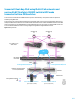
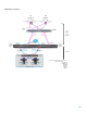
HP 5900CP Switch configuration
Details about the HP 5900CP configuration:
NPV mode is used.
Interfaces XGE1/0/12-14 are connected to the VC modules thought FCoE using a bridge aggregation BAGG 20.
Interfaces fc1/0/35 and fc1/0/36 are connected to MDS Core switches using NPIV (NP_Ports).
Interface fc1/0/35 is mapped to VSAN 200/201 and fc1/0/36 to VSAN 300/301 (Alternativelly, you can assign both
interfaces to all VSANs).
VLAN IDs 200/300 and 201/301 are used for the FCoE networks.
VSAN 200/300 and 201/301 are used for the FCoE traffic.
VLAN 200 maps to VSAN 200, VLAN 300 to VSAN 300, VLAN 201 to VSAN 201 and VLAN 301 to VSAN 301
Interfaces XGE1/0/15 are connected to the datacenter LAN.
VLAN IDs 1, 10 and 20 are the standard Ethernet networks (non-FCoE networks).
The virtual Fibre Channel interfaces vfc 1 bind to the MAC addresses of the first Blade server.
The virtual Fibre Channel interfaces vfc 2 bind to the MAC addresses of the second Blade server.
The EVA is connected to VSAN 30x and the 3PAR is connected to VSANs 20x.
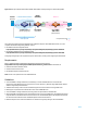
Details about the MDS 9148 configuration:
FCF mode is used.
Interfaces fc1/9 and fc1/10 are connected to the 5900CP switches thought FC (F_Ports).
VSANs 200/300 are defined on the first fabric and VSANs 201/301 on the second one.
Interfaces fc1/1 are connected to the EVA and fc1/2 are connected to the 3PAR.
The EVA is connected to VSAN 30x and the 3PAR is connected to VSANs 20x.