Technical white paper HP Virtual Connect 1Gb Ethernet Cookbook (Version 3.30 through 3.60 Firmware Enhancements) Purpose Documentation feedback 3 3 Introduction to Virtual Connect 1Gb Ethernet Networking New Features: vNets, Tunnels and Shared Uplink Sets Determining Network Traffic Patterns (North/South and East/West) and Virtual Connect network design (Active/Active vs.
Scenario 4 – VLAN Tagging (802.1Q) with a Shared Uplink Set (SUS) with Link Aggregation using LACP (802.3ad) – Windows Overview Requirements Configuring Uplinks to a SUS (LACP) Installation and configuration Summary Results 47 47 47 47 49 55 55 Scenario 5 – VLAN Tagging (802.1Q) with a Shared Uplink Set (SUS) with Link Aggregation using LACP (802.
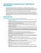
Purpose The purpose of this Virtual Connect Cookbook is to provide users of Virtual Connect with a better understanding of the concepts and steps required when integrating HP BladeSystem and Virtual Connect components into an existing network. This document will focus specifically on the Virtual Connect 1Gb Ethernet modules as installed in the c7000 BladeSystem enclosure.
Introduction to Virtual Connect 1Gb Ethernet Networking Virtual Connect is an industry standard-based implementation of server-edge virtualization. It puts an abstraction layer between the servers and the external networks so the LAN and SAN see a pool of servers rather than individual servers (Figure 1).
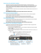
is displayed if an unsupported DAC cable is attached to any of the uplink ports X1–X4. This limitation is documented in the QuickSpecs and the HP Virtual Connect for c-Class BladeSystem Setup and Installation Guide. Improved integration with HP System Insight Manager. The HP VC 8Gb 20-Port FC Module firmware is now correctly returning several important elements of the HP MIBs as part of the System Insight Manager discovery. Virtual Connect Firmware 3.
Virtual Connect Flex-10/FlexFabric Cookbook Virtual Connect can be used to support both Ethernet and FCoE connections. The Virtual Connect Flex10/FlexFabric Cookbook is provided with basic Virtual Connect configurations for both 10Gb and 10Gb with FCoE solutions, whereas the Virtual Connect 1Gb Ethernet Cookbook (this paper) provides 1Gb scenarios only. If you are new to Virtual Connect and will be utilizing Flex-10 or FlexFabric it is highly recommended that you also review that document.
Tunneled VLAN and Mapped VLANS Readers that are familiar with earlier releases of Virtual Connect firmware features will realize that VC 3.30 firmware removed the need to configure VC in Mapped vs. Tunneled mode. As of VC 3.30 firmware release, VC now provides the ability to simultaneously take advantage of the features and capabilities that were provided in either mapped or tunneled modes, there is no need to choose the domain’s mode of operation.
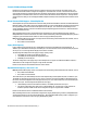
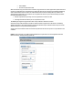
If the above noted 1Gb VC modules are inserted into an enclosure that is in Expanded VLAN Capacity mode, they are marked as incompatible. If these modules are installed in an enclosure, converting to Expanded VLAN Capacity mode will not be permitted. Figure 2 - Configuring Expanded VLAN Capacity support.
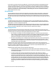
If you create a new network access group, NetGroup1, and move existing networks from the Default network access group to NetGroup1, then a profile that uses NetGroup1 cannot use networks included in the Default network access group. Similarly, if you create a new network and assign it to NetGroup1 but not to the Default network access group, then a profile that uses the Default network access group cannot use the new network.
PVST+ BPDUs Procurve Loop Protect frames When the network loop protection feature is enabled, any probe frame or other supported loop detection frame received on a downlink port is considered to be causing the network loop, and the port is disabled immediately until an administrative action is taken. The administrative action involves resolving the loop condition and clearing the loop protection error condition.
Bulk VLAN Creation In addition to providing support for a greater number of VLANs, VC now provides the ability to create several VLANs, within a Shared Uplink Set (SUS), in a single operation. Using the Bulk VLAN creation feature in the GUI or the add network-range command in the CLI many VLANs can be added to a SUS in a single operation. In addition, copying an existing SUS is also now possible. When creating an Active/Active SUS configuration, you can create the first SUS, and then copy it.
vNets, Tunnels and Shared Uplink Sets vNet There are two types of vNets. The first is a simple vNet that will pass only untagged frames. The second is a vNet tunnel which will pass tagged frames for one or many VLANs. The vNet is a simple network connection between one or many server NICs to one or many uplink ports.
With Mapped VLAN Tags, you can create a Shared Uplink Set that contains ALL the VLANs you want to present to your servers, then present only ONE network (the one associated with the VLAN we want the server NIC in) to the Windows, LINUX or the ESX Console NIC, then select Multiple Networks for the NIC connected to the ESX vSwitch and select ALL the networks that we want presented to the ESX host vSwitch. The vSwitch will then break out the VLANs into port groups and present them to the guests.
Single Domain/Enclosure Scenarios Overview This chapter will provide several simple configuration scenarios of Virtual Connect, using a Single HP BladeSystem c7000 enclosure with two Virtual Connect Ethernet modules installed in Bays 1 and 2. Each scenario will provide an overview of the configuration, show how to complete that configuration and include both GUI and CLI (scripted) methods. Where possible, examples for Windows and/or VMware will also be provided.
Scenario 1 – Simple vNet with Active/Standby Uplinks and Optional Link Aggregation 802.3ad (LACP) - Windows Overview This simple configuration uses the Virtual Connect vNet. The vNet is the simplest way to connect Virtual Connect to a network and server. In this scenario, the upstream network switch connects a network to a single port on each VC module. No special upstream switch configuration is required as the switch is in the factory default configuration, typically configured as Access ports.
Figure 6 - Physical View; Shows a single Ethernet uplink from Port 1 on Module 1 to Port 1 on the first network switch and a single uplink from Port 1 on Module 2 to Port 1 on the second network switch. Figure 7 - Logical View; Shows a single Ethernet uplink from Port 1 on Module 1 on the first network switch and a single uplink from Port 1 on Module 2 to Port 1 on the second network switch. A single vNet is configured and connected to both switches.
Installation and configuration Switch configuration Appendices A and B provide a summary of the commands required to configure the switch in either a Cisco IOS or a ProCurve network infrastructure. The configuration information provided in the appendices assumes the following information: The switch ports are configured as ACCESS ports, either presenting the Default VLAN or a specific VLAN and will forward (only) untagged frames.
Note: By connecting TWO Uplinks from this vNet we have provided a redundant path to the network. As each uplink originates from a different VC module, one uplink will be Active and the second will be in Standby. This configuration provides the ability to lose an uplink cable, network switch or depending on how the NICs are configured at the server (teamed or un-teamed), even a VC module. Note: In this configuration Smartlink should NOT be enabled.
Defining a Server Profile with NIC Connections, via CLI The following command(s) can be copied and pasted into an SSH based CLI session with Virtual Connect # Create and Assign Server Profile App-1 to server bay 1 add profile App-1 -nodefaultenetconn add enet-connection App-1 pxe=Enabled add enet-connection App-1 pxe=Disabled set enet-connection App-1 1 Network=vNet-PROD set enet-connection App-1 2 Network=vNet-PROD assign profile App-1 enc0:1 Figure 9 - Define Server Profile (App- 1).
Figure 10 - Server Profile View Bay 1. Optionally Configuring Additional Uplinks to a vNet (LACP) If additional uplink bandwidth or redundancy is required, uplinks can be added it an existing vNet. There are two options available when configuring additional uplinks, when all uplinks configured within a vNet connect a single VC module to a single upstream switch, ALL links will be active, providing additional bandwidth, using Link Aggregation Protocol (LACP 802.
Figure 11- Shows two Ethernet uplinks from Port 1 and 2 on Module 1 to Port 1 and 2 on the first network switch and two uplinks from ports 1 and 2 on Module 2 to Ports 1 and 2 on the second network switch. Figure 12 - Logical View; Shows two Ethernet uplinks from Ports 1& 2 of each VC module to the network switch. A single vNet is configured and connected to both switches.
Adding uplinks to an existing vNet via GUI Edit the vNet named “vNet-PROD” In the left pane of the Virtual Connect Manager screen, click on the Network “vNet-Prod” Select Add Port, then add the following ports; Enclosure 1, Bay 1, Port 2 Enclosure 1, Bay 2, Port 2 Leave Connection Mode as Auto Select Apply Note: By connecting FOUR Uplinks from this vNet we have provided additional bandwidth and a redundant path to the network as two uplinks will be active and two will be in standby.
Figure 14 - Link aggregation confirmed – Bay 1. Note: All connections within an active/active LACP group will have the same LAG ID. To view this, go to the Interconnect bay and view Uplink Port Information. If you are having trouble establishing an active/active connection, confirm the LAG ID. Figure 15 - Link aggregation confirmed - Bay 2. Summary We created a couple different Virtual Connect Network solutions; based initially for availability, one link was active while the second was in standby mode.
Resu ults The follo owing graphicss provides examples of a Win ndows 2008R22 Server with T TWO NICs conn nected to the ne etwork. Initially, each NIC ha as its own TCP//IP address, eitther or both NICs could be actively working on the network. Ad dditional examples are show n when using N NIC teaming. Figure 16 - Both NICs for f Profile App p-1are connectted to the netw work through vvNet-PROD.
Figure 18 - Both NICs for Profile App-1are teamed and connected to the network through vNetPROD. Scenario 1 – Simple vNet with Active/Standby Uplinks and Optional Link Aggregation 802.
Scenario 2 – Multiple Simple Networks with Active\Active Uplinks Link Aggregation 802.3ad (LACP) - Windows Overview This simple configuration uses the Virtual Connect vNet. The vNet is the simplest way to connect Virtual Connect to a network and server. In this scenario, the upstream network switch connects a network to a single port on each VC module. No special upstream switch configuration is required as the switch is in the factory default configuration.
Figure 19 - Physical View; Shows a single Ethernet uplink from Port 1 on Module 1 to Port 1 on the first network switch and a single uplink from Port 1 on Module 2 to Port 1 on the second network switch. Figure 20 - Logical View; Shows a single Ethernet uplink from Port 1 on Module 1 on the first network switch and a single uplink from Port 1 on Module 2 to Port 1 on the second network switch. Scenario 2 – Multiple Simple Networks with Active\Active Uplinks Link Aggregation 802.
Installation and configuration Switch configuration Appendices A and B provide a summary of the commands required to configure the switch in either a Cisco IOS or a ProCurve network infrastructure. The configuration information provided in the appendices assumes the following information: The switch ports are configured as ACCESS ports, either presenting the Default VLAN or a specific VLAN and will forward (only) untagged frames.
or depending on how the NICs are configured at the server (teamed or un-teamed), even a VC module. Note: In this configuration Smartlink should be enabled. Smartlink is used to turn off downlink ports within Virtual Connect, if ALL available uplinks to a vNet or SUS are down, thus initiating a teaming fail-over. Defining a new vNet via CLI The following command(s) can be copied and pasted into an SSH based CLI session with Virtual Connect.
Defining a Server Profile with NIC Connections, via CLI The following command(s) can be copied and pasted into an SSH based CLI session with Virtual Connect. # Create and Assign Server Profile App-1 to server bay 1 add profile App-1 -nodefaultenetconn add enet-connection App-1 pxe=Enabled add enet-connection App-1 pxe=Disabled set enet-connection App-1 1 Network=vNet-PROD-1 set enet-connection App-1 2 Network=vNet-PROD-2 assign profile App-1 enc0:1 Figure 22 - Define Server Profile (App- 1).
Figure 23 - Server Profile View Bay 1. Optionally Configuring Additional Uplinks to a vNet (LACP) If additional uplink bandwidth or redundancy is required, uplinks can be added it an existing vNet. There are two options available when configuring additional uplinks, when all uplinks configured within a vNet connect a single VC module to a single upstream switch, ALL links will be active, providing additional bandwidth, using Link Aggregation Protocol (LACP 802.
Figure 24 - Shows two Ethernet uplinkks from Port 1 and 2 on Moduule 1 to Port 1 and 2 on the ffirst network sw witch and two uplinks from ports p 1 and 2 on o Module 2 too Ports 1 and 2 on the second d network sw witch. Figure 25 - Logical View;; Shows two Etthernet uplinks from Ports 1 & 2 of each VCC module to the network sw witch. Swittch configurration (LACP P) Appendices A and B provide a summary of the com mmands requireed to configure the switch in n work infrastruccture.
Adding uplinks to an existing vNet via GUI Edit the vNet named “vNet-PROD-1” In the left pane of the Virtual Connect Manager screen, click on the Network “vNet-Prod-1” Select Add Port, then add the following ports; Enclosure 1, Bay 1, Port 2 Leave Connection Mode as Auto Enable Smart Link Select Apply Edit the vNet named “vNet-PROD-2” In the left pane of the Virtual Connect Manager screen, click on the Network “vNet-Prod-2” Select Add Port, then add the following ports; Enclosure
Note: The Port Status and Connected to information. If the connected switch supports LLDP, the connected to information should be displayed as below. Figure 27 - Link aggregation confirmed – Bay 1. Note: All connections within an active/active LACP group will have the same LAG ID. To view this, go to the Interconnect bay and view Uplink Port Information.
Resu ults The follo owing graphicss provides examples of a Win ndows 2008R22 Server with T TWO NICs conn nected to the ne etwork. Initially, each NIC ha as its own TCP//IP address, eitther or both NICs could be actively working on the network. Ad dditional examples are show n when using N NIC teaming. Figure 28 2 - Both NICs for f Profile App p-1are connectted to the netw work through vvNet-PROD 1 aand vNetPRO OD-2 networkss.
Figure 30 - Both NICs for Profile App-1are teamed and connected to the network through vNetPROD-1 and vNet-PROD-2. Scenario 2 – Multiple Simple Networks with Active\Active Uplinks Link Aggregation 802.
Scenario 3 – Multiple Simple Networks Providing Redundancy and Link Aggregation 802.3ad (LACP) with VLAN Tunneling – VMware ESX Overview This configuration uses the Virtual Connect vNet Tunnel. The vNet Tunnel will accept and forward tagged frames between servers and uplinks. With a vNet Tunnel Virtual Connect does not make forwarding decisions based on the VLAN Tag, instead all server NICs connected to the vNet Tunnel will receive ALL frames, much like a VLAN Trunked switch port.
Figure 31 3 - Physical Viiew; Shows two Ethernet upllinks from Portts 1 & 2 on Module 1 to Portss 1 & 2 on the first network switch and two uplinks from m Ports 1 and 2 on Module 2 tto Ports 1 & 2 on ond network sw witch. the seco Figure 32 3 - Logical Vie ew; Shows two Ethernet uplin nks from Portss 1&2 of each V VC module to tthe network k switches. ks Providing Red dundancy and Link Aggregation 802.
Installation and configuration Switch configuration Appendices A and B provide a summary of the commands required to configure the switch in either a Cisco IOS or a ProCurve network infrastructure. The configuration information provided in the appendices assumes the following information: The upstream switch ports are configured as TRUNK ports, presenting VLANs 1, 101-105 and 21012150. Note: VLAN 101 is set to default (untagged).
Enable VLAN Tunneling Leave Connection Mode as Auto Select Apply Note: By connecting ONE Uplink from each vNet we have provided a redundant path to the network. As each uplink originates from a different VC module and provided connectivity for its own vNet. All uplinks will be Active. This configuration provides the ability to lose an uplink cable, network switch or depending on how the NICs are configured at the server (teamed or un-teamed), even a VC module.
Figure 34 - Link aggregation confirmed – Bay 1. Note: All connections within an active/active LACP group will have the same LAG ID. To view this, go to the Interconnect bay and view Uplink Port Information. If you are having troubles establishing an active/active connection, confirm the LAG ID. Defining a Server Profile with NIC Connections, via GUI Each server NIC will connect to a specific network.
Figure 35 - Define a Server Profile (ESX-1). Figure 36 – ESX-1 Profile – Bay View. Scenario 3 – Multiple Simple Networks Providing Redundancy and Link Aggregation 802.
Summary We created two VC networks, both with TWO active uplinks. Both VC Networks will pass several VLANs as configured/defined by the connected switch, without modification or interpreting the VLAN tags. When VC profile ESX-1 is applied to the server in bay1 and is powered up, it has two NICs, these NICs are connected to “vNet-PROD-1” and “vNet-PROD-2” respectively, which connects to the network infrastructure through uplinks.
Figure 38 - Both NICs for Profile ESX-1are connected to the network through vNet=PROD-1 and vNet-PROD-2, VLANs are configured as Port Groups within the virtual switch. Note: As VLAN 101 is set as untagged at the upstream switch port, the management network port group should be defined as untagged. This will allow the server to be deployed, without having the set a VLAN ID for the management network. Figure 39 - Configuring the ESX vSwitch for Multiple Networks / VLANs.
Figure 40 – You may want to specify a specific NIC for VMotion traffic. This will ensure that all VMotion traffic between servers within the enclosure will remain on the same VC module, reducing the likelihood of multiple hops between servers. By setting the second adapter to standby, VMotion traffic will remain on vmnic0 (VC module Bay 1) and will only use vmnic1 if a failure were to occur.
When configuring the virtual guest, edit the Network Adapter configuration and select which VLAN this guest will connect to. Figure 41 – Set the Guest VM to the appropriate VLAN. Figure 42 - Windows VM Guest configured in VLAN 102. Scenario 3 – Multiple Simple Networks Providing Redundancy and Link Aggregation 802.
Scenario 4 – VLAN Tagging (802.1Q) with a Shared Uplink Set (SUS) with Link Aggregation using LACP (802.3ad) – Windows Overview This configuration uses the Virtual Connect Shared Uplink Set (SUS). The SUS provides the ability to present a single or multiple VLANs to a server NIC. In this scenario, the upstream network switch connects multiple VLANs to two ports on each VC module. The single SUS is a popular configuration when supporting primarily East/West traffic patterns.
Figure 43 4 - Shows two o Ethernet uplinks from Port 1 and 2 on Moodule 1 to Portt 1 and 2 on thee first network k switch and tw wo uplinks from m ports 1 and 2 on Module 2 to Ports 1 andd 2 on the seco ond network k switch. Figure 44 4 - Logical Vie ew; Shows two Ethernet uplin nks from each VC module to the network switchess. The Uplinks from both Mo odules are asso ociated with thhe Shared Uplinnk Set “VLANTrunk.
Installation and configuration Switch configuration Appendices A and B provide a summary of the commands required to configure the switch in either a Cisco IOS or a ProCurve network infrastructure. The configuration information provided in the appendices assumes the following information: The upstream switch ports are configured as TRUNK ports, presenting VLANs 1, 101-105 and 21012150. Note: VLAN 101 is set to default (untagged).
Figure 45 - Ethernet Settings - Ensure Fast MAC Cache is enabled.
Defining a new Shared Uplink Set via CLI #Create Shared Uplink Set "VLAN-Trunk" and configure uplinks 1 and 2 from each VC-F module add uplinkset VLAN-Trunk add uplinkport enc0:1:1 Uplinkset=VLAN-Trunk speed=auto add uplinkport enc0:1:2 Uplinkset=VLAN-Trunk speed=auto add uplinkport enc0:2:1 Uplinkset=VLAN-Trunk speed=auto add uplinkport enc0:2:2 Uplinkset=VLAN-Trunk speed=auto # Create Networks VLAN-1, 102-105 and 2101-2150 for Shared Uplink Set "VLAN-TRUNK" add network VLAN-101 uplinkset=VLAN-Trunk VLanID
Figure 47 - VLAN-Trunk Link aggregation confirmed – Bay 1. Note: All connections within an LACP group will have the same LAG ID. To view this, go to the Interconnect bay and view Uplink Port Information. If you are having troubles establishing an active/active connection, confirm the LAG ID. Scenario 4 – VLAN Tagging (802.1Q) with a Shared Uplink Set (SUS) with Link Aggregation using LACP (802.
Figure 48 - VLAN-Trunk Link aggregation confirmed – Bay 2. Note: All connections within an LACP group will have the same LAG ID. To view this, go to the Interconnect bay and view Uplink Port Information. If you are having troubles establishing an active/active connection, confirm the LAG ID. Defining a Server Profile with NICs Connections to a single VLAN, via GUI Each server NIC will connect to a network.
Figure 49 - Define a Server Profile App-1, connected to VLAN-102. Figure 50 - View Bay - Note VLAN-102. Scenario 4 – VLAN Tagging (802.1Q) with a Shared Uplink Set (SUS) with Link Aggregation using LACP (802.
Su ummary We creatted a Virtual Co onnect Shared d Uplink Set (SU US), to supportt several VLAN Ns (1, 101-105, 2101-21 150). The SUS was created with w both Active and standbyy uplinks, to provide both addition nal bandwidth and a availabilityy, LACP was ussed to provide additional banndwidth. When VC C profile App-1 is applied to the t server in bay2 and is pow wered up, it haas two NICs connecte ed to “VLAN-102”, which con nnects to the network n infrasttructure throuugh two (activee) 1Gb uplinks.
The follo owing graphicss provide an exxample of a Wiindows 2008R R2 Server with TWO NICs team med and conn nected to the network. n One NIC will be active, the other in standby, in tthe event of an Uplink or switch failure e, VC would fail-over the upllinks and the server would no ot be affected by ure, however, iff the VC modulle with the active uplinks weere to fail, the tteaming softw ware the failu will fail the t NIC over to o the alternate path, as requiired.
Scenario 5 – VLAN Tagging (802.1Q) with a Shared Uplink Set (SUS) with Link Aggregation using LACP (802.3ad) – VMware ESX Overview This configuration uses single Virtual Connect Shared Uplink Set (SUS). The SUS provides the ability to present a single or multiple VLANs to a server NIC. In this scenario, the upstream network switch connects multiple VLANs to two ports on each VC module. The single SUS is a popular configuration when supporting primarily East/West traffic patterns.
Figure 54 5 - Shows two o Ethernet uplinks from Port 1 and 2 on Moodule 1 to Portt 1 and 2 on thee first network k switch and tw wo uplinks from m ports 1 and 2 on Module 2 to Ports 1 andd 2 on the seco ond network k switch. Figure 55 5 - Logical Vie ew; Shows two Ethernet uplin nks from each VC module to the network switchess. The Uplinks from both Mo odules are asso ociated with thhe Shared Uplinnk Set “VLANTrunk.
Installation and configuration Switch configuration Appendices A and B provide a summary of the commands required to configure the switch in either a Cisco IOS or a ProCurve network infrastructure. The configuration information provided in the appendices assumes the following information: The upstream switch ports are configured as TRUNK ports, presenting VLANs 1, 101-105 and 21012150. Note: VLAN 101 is set to default (untagged).
Figure 56 - Ethernet Settings - Ensure Fast MAC Cache is enabled.
depending on how the NICs are configured at the server (teamed or unteamed), even a VC module. However, only one uplink pair will be active at a time. Note: Smart Link – In this configuration Smartlink should NOT be enabled. Smartlink is used to turn off downlink ports within Virtual Connect network, if ALL available uplinks to that network are down.
Figure 58 - VLAN-Trunk Link aggregation confirmed – Bay 1. Note: All connections within an LACP group will have the same LAG ID. To view this, go to the Interconnect bay and view Uplink Port Information. If you are having troubles establishing an active/active connection, confirm the LAG ID. Scenario 5 – VLAN Tagging (802.1Q) with a Shared Uplink Set (SUS) with Link Aggregation using LACP (802.
Figure 59 - VLAN-Trunk Link aggregation confirmed – Bay 2. Note: All connections within an LACP group will have the same LAG ID. To view this, go to the Interconnect bay and view Uplink Port Information. If you are having troubles establishing an active/active connection, confirm the LAG ID. Defining a Server Profile with NICs Connections to multiple VLANs, via GUI Each server NIC will connect to a network.
Defining a Server Profile with NICs Connections to multiple VLANs, via CLI The following command(s) can be copied and pasted into an SSH based CLI session with Virtual Connect # Create and Assign Server Profile ESX-1 add profile ESX-1 -nodefaultfcconn -nodefaultfcoeconn add server-port-map-range ESX-1:1 UplinkSet=VLAN-Trunk VLanIds=101-105,2101,2110,2120 set server-port-map ESX-1:1 VLAN-101 UnTagged=true set enet-connection ESX-1 1 pxe=Enabled add server-port-map-range ESX-1:2 UplinkSet=VLAN-Trunk VLanIds=1
Figure 61 - Select the VLANs to be configured for this NIC, also note only ONE VLAN can be defined as Untagged. Figure 62 - View Bay - Note Multiple VLAN Connections. Scenario 5 – VLAN Tagging (802.1Q) with a Shared Uplink Set (SUS) with Link Aggregation using LACP (802.
Summary We created a Virtual Connect Shared Uplink Set (SUS), to support several VLANs (1, 101-105, 2101-2150). The SUS was created with both Active and Standby uplinks, to provide both additional bandwidth and availability. In addition, the single SUS was used to promote better East/West traffic patterns between servers within the same VLAN.
Figure 64 - Both NICs for Profile ESX-1are connected to the network through the SUS VLANTrunk, VLANs are configured as Port Groups within the virtual switch. Note: As VLAN 101 is set as untagged at the Server profile, the management network port group should be defined as untagged. This will allow the server to be deployed, without having to set the a VLAN ID for the management network.
Figure 66 - Configuring the ESX vSwitch for Multiple Networks / VLANs. If additional VLANs need to be supported, simply configure the upstream switch ports for those VLANs, add them to the SUS and configure the vSwitch as below to support those additional VLANs. Note: Ensure that the vSwitch Network Failover Detection is set to “Link Status only”. If a VC module were to fail, this will ensure that vSwitch fails over to the alternate NIC. Scenario 5 – VLAN Tagging (802.
Figure 67 – To speed VMotion events and to ensure that ALL VMotion traffic between servers within the enclosure is contained on the same VC module, on each server edit the VMotion vSwitch properties and move one of the Adapters to Standby. Note: By ensuring that ALL servers within an enclosure use the SAME NIC, which in turn would be connected to the SAME I/O Bay, we can ensure that ALL VMotion traffic will occur on the same Virtual Connect module. Scenario 5 – VLAN Tagging (802.
When configuring the virtual guest, edit the Network Adapter configuration and select which VLAN this guest will connect to. Figure 68 – Set the Guest VM to the appropriate VLAN. Figure 69 - Windows VM Guest configured in VLAN 102. Scenario 5 – VLAN Tagging (802.1Q) with a Shared Uplink Set (SUS) with Link Aggregation using LACP (802.
Scenario 6 – VLAN Tagging (802.1Q) with Multiple Shared Uplink Sets (SUS) and Link Aggregation using LACP (802.3ad) – VMware ESX Overview In this scenario, the upstream network switch connects multiple VLANs to two ports on each VC module. This scenario configuration uses TWO Virtual Connect Shared Uplink Sets (SUS). The SUS provides the ability to present a single or multiple VLANs to a server NIC.
Figure 70 7 - Shows two o Ethernet uplinks from Port 1 and 2 on Moodule 1 to Portt 1 and 2 on thee first network k switch and tw wo uplinks from m ports 1 and 2 on Module 2 to Ports 1 andd 2 on the seco ond network k switch. Figure 71 7 - Logical Vie ew; Shows two Ethernet uplin nks from each VC module to the network switchess. The Uplinks from each Mo odule are assocciated with thee Shared Uplink Sets “VLANTrunk-1 and VLAN-Tru unk-2.
Installation and configuration Switch configuration Appendices A and B provide a summary of the commands required to configure the switch in either a Cisco IOS or a ProCurve network infrastructure. The configuration information provided in the appendices assumes the following information: The upstream switch ports are configured as TRUNK ports, presenting VLANs 1, 101-105 and 21012150. Note: VLAN 101 is set to default (untagged).
Defining a new Shared Uplink Set via CLI #Create Shared Uplink Set "VLAN-Trunk-1" and configure uplinks 1 and 2 from the VC-F module in Bay 1 add uplinkset VLAN-Trunk-1 add uplinkport enc0:1:1 Uplinkset=VLAN-Trunk-1 speed=auto add uplinkport enc0:1:2 Uplinkset=VLAN-Trunk-1 speed=auto # Create Networks VLAN-1-1, VLAN-101-105-1 and 2101-2150-1 for Shared Uplink Set "VLANTRUNK-1" add network VLAN-101-1 uplinkset=VLAN-Trunk-1 VLanID=101 NativeVLAN=Enabled Set Network VLAN-101-1 SmartLink=Enabled add network-ran
Figure 73 - VLAN-Trunk Link aggregation confirmed – Bay 1. Note: All connections within an LACP group will have the same LAG ID. To view this, go to the Interconnect bay and view Uplink Port Information. If you are having troubles establishing an active/active connection, confirm the LAG ID. If the LAG ID is not the same, you likely have a LACP configuration issue with the upstream switch. Scenario 6 – VLAN Tagging (802.1Q) with Multiple Shared Uplink Sets (SUS) and Link Aggregation using LACP (802.
Figure 74 - VLAN-Trunk-2 Link aggregation confirmed – Bay 2. Note: All connections within an LACP group will have the same LAG ID. To view this, go to the Interconnect bay and view Uplink Port Information. If you are having troubles establishing an active/active connection, confirm the LAG ID. If the LAG ID is not the same, you likely have a LACP configuration issue with the upstream switch.
Defining a Server Profile with NICs Connections to a multiple VLANs, via CLI The following command(s) can be copied and pasted into an SSH based CLI session with Virtual Connect # Create and Assign Server Profile ESX-1 add profile ESX-1 -nodefaultfcconn -nodefaultfcoeconn add server-port-map-range ESX-1:1 UplinkSet=VLAN-Trunk-1 VLanIds=101105,2101,2110,2120 set server-port-map ESX-1:1 VLAN-101-1 UnTagged=true set enet-connection ESX-1 1 pxe=Enabled add server-port-map-range ESX-1:2 UplinkSet=VLAN-Trunk-2 VL
Figure 76 - Select the VLANs to be configured for this NIC, also note only ONE VLAN can be defined as Untagged. Figure 77 - View Bay - Note Multiple VLAN Connections. Scenario 6 – VLAN Tagging (802.1Q) with Multiple Shared Uplink Sets (SUS) and Link Aggregation using LACP (802.
Summary We created two independent but identical Shared Uplink Sets (SUS), to support several VLANs (1, 101-105, 2101-2150). Each SUS was created with Active uplinks, to provide both additional bandwidth and availability. When VC profile ESX-1 is applied to the server in bay1 and is powered up, it has two NICs each connected to “Multiple VLANs”, which connects to the network infrastructure through two (active) 1Gb uplinks.
Figure 79 - Both NICs for Profile ESX-1 are connected to the network through Multiple Networks; VLANs are configured as Port Groups within the virtual switch. Note: As VLAN 101 is set as untagged at the Server profile, the management network port group should be defined as untagged. This will allow the server to be deployed, without having to set a VLAN ID for the management network. Figure 80 - Configuring the ESX vSwitch for Multiple Networks / VLANs.
Figure 81 - Configuring the ESX vSwitch for Multiple Networks / VLANs. If additional VLANs need to be supported, simply configure the upstream switch ports for those VLANs, then configure the vSwitch as below to support those additional VLANs. Note: As this Scenario is based on an Active/Active configuration, to ensure that ALL VMotion traffic between servers within the enclosure is contained, on each server edit the VMotion vSwitch properties and move one of the Adapters to Standby.
When configuring the virtual guest, edit the Network Adapter configuration and select which VLAN this guest will connect to. Figure 82 – Set the Guest VM to the appropriate VLAN. Figure 83 - Windows VM Guest configured in VLAN 102. Scenario 6 – VLAN Tagging (802.1Q) with Multiple Shared Uplink Sets (SUS) and Link Aggregation using LACP (802.
Appendix A: Scenario-based Cisco command line reference All of the following commands in this appendix assume an unaltered factory default configuration before execution of the switch commands. Scenario 1 & 2 – Cisco IOS command line configuration (Simple vNet with Active/Standby Uplinks) Connect to the Cisco switch servicing the VC-Enet uplink ports and enter the following IOS commands. NOTE: If two switches are being used, issue the same commands on the second switch.
Simple vNet with Active/Standby Uplinks and Link Aggregation 802.3ad (LACP) - Windows Connect to the Cisco switch servicing the VC-Enet uplink ports and enter the following IOS commands. NOTE: If two switches are being used, issue the same commands on the second switch. Table 1b Scenario 1 and 2 (Part 2) - Cisco IOS command line configuration.
Table 1b Scenario 1 and 2 (Part 2) - Cisco IOS command line configuration.
Scenario 3-6 – Cisco IOS command line configuration (Multiple Simple Networks Providing Redundancy and Link Aggregation 802.3ad (LACP)) Connect to the Cisco switch servicing the VC-Enet uplink ports and enter the following IOS commands. NOTE: If two switches are being used, issue the same commands on the second switch. Table 2 Scenario 3 – 6 Cisco IOS command line configuration (802.1Q, 802.3ad).
Table 2 Scenario 3 – 6 Cisco IOS command line configuration (802.1Q, 802.3ad).
Appendix B: Scenario-based ProCurve command line reference Scenario 1 & 2 – ProCurve command line configuration (Simple vNet with Active/Standby Uplinks) Connect to the ProCurve switch servicing the VC-Enet uplink ports and enter the following commands. NOTE: If two switches are being used, issue the same commands on the second switch. Table 3a Scenario 1 & 2 (Part 1) - ProCurve command line configuration (simple network).
Simple vNet with Active/Standby Uplinks and Link Aggregation 802.3ad (LACP) Connect to the ProCurve switch servicing the VC-Enet uplink ports and enter the following commands. NOTE: If two switches are being used, issue the same commands on the second switch. Table 3b Scenario 1 &2 2 (Part 2) - ProCurve command line configuration (simple network, 1 untagged VLAN ).
Scenario 3-6 – ProCurve command line configuration (Multiple Simple Networks Providing Redundancy and Link Aggregation 802.3ad (LACP)) Connect to the ProCurve switch servicing the VC-Enet uplink ports and enter the following commands. NOTE: If two switches are being used, issue the same commands on the second switch. Table 4 Scenario 3-6 - ProCurve command line configuration (Tagged VLANs).
Table 4 Scenario 3-6 - ProCurve command line configuration (Tagged VLANs). Command Shortcut Description #spanning-tree ethernet trk1 adminedge-port #span e trk1 adminedge Set Port 1 to be an edge port (non bridging port). Note: port is set by default in “autoedge” mode which automatically sets port to Edge if no BPDU are received after 3 sec.
Appendix C: Acronyms and abbreviations Term Definition Auto Port Speed** Let VC automatically determine best Flex NIC speed CLP String Flex-10 NIC settings written to the server hardware by VC/OA when the server is power off. Read by the server hardware upon power in. Custom Port Speed** Manually set Flex NIC speed (up to Maximum value defined) DCC** Dynamic Control Channel.
Appendix D: Useful VC CLI Command sets The following are a collection of useful VC CLI commands. These CLI commands and many more are documented in detail in Virtual Connect Manager Command Line Interface Version 1.31 (or later) User Guide. The following CLI commands can be copied and pasted into an SSH session with the VCM and will apply immediately upon paste.
# Create Networks PROD-A through PROD-D, supporting VLANs 101 through 104 on Shared Uplink Set "ProdNet" add network VLAN_10 uplinkset=Prod-Net VLanID=10 add network VLAN_20 uplinkset=Prod-Net VLanID=20 # (optionally) Set network VLAN_20 as a “Private Network” set network VLAN20 Private=Enabled Creating vNets #Create vNet "Prod-Net" and configure uplinks add Network Prod-Net add uplinkport enc0:1:3 Network=Prod-Net speed=auto #Optionally enable the vNet as a Private Network set network Prod-Net Private=Enab
# Create Server Profile Server-1 with Flex-10 NICs configured for specific speeds add profile Server-1 -nodefaultenetconn add enet-connection Server-1 pxe=Enabled Network=Console-101-1 SpeedType=Custom Speed=500 add enet-connection Server-1 pxe=Disabled Network=Console-101-2 SpeedType=Custom Speed=500 add enet-connection Server-1 pxe=Disabled Network=VMotion-102-1 SpeedType=Custom Speed=2500 add enet-connection Server-1 pxe=Disabled Network=VMotion-102-2 SpeedType=Custom Speed=2500 add enet-connection Serve
For more information To read more about Virtual Connect, go to: hp.com/go/virtualconnect Get connected hp.com/go/getconnected © Copyright 2012 Hewlett-Packard Development Company, L.P. The information contained herein is subject to change without notice. The only warranties for HP products and services are set forth in the express warranty statements accompanying such products and services. Nothing herein should be construed as constituting an additional warranty.