
HP Virtual Connect 1Gb Ethernet Cookbook

Scenario 2 – Multiple Simple Networks with Active\Active Uplinks Link Aggregation 802.3ad (LACP) - Windows 28
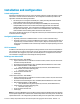
Installation and configuration
Switch configuration
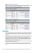
Appendices A and B provide a summary of the commands required to configure the switch in either
a Cisco IOS or a ProCurve network infrastructure. The configuration information provided in the
appendices assumes the following information:
The switch ports are configured as ACCESS ports, either presenting the Default VLAN or a
specific VLAN and will forward (only) untagged frames.
As an alternative, if the switch ports were configured as TRUNK ports and forwarding
multiple VLANS, Virtual Connect would forward those tagged frames to the host NICs
configured for this network. The connected host would then need to be configured to
interpret those VLAN tags. Note: for a vNet to forward TAGGED frames, vNet Tunneling
must be enabled. vNet Tunneling will be discussed in a later Scenario.
This scenario assumes the switch port is configured as an Access port and the frames are presented
to Virtual Connect as untagged.
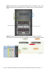
Configuring the VC module
Physically connect Port 1 of Network switch 1 to Port 1 on the VC module in Bay 1.
Physically connect Port 1 of the second Network switch to Port 1 of the VC module in Bay 2,
if you have only one network switch, connect VC port 1 (Bay 2) to an alternate port on the
same switch. This will NOT create a network loop and does not require Spanning Tree to be
configured.
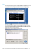
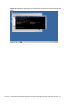
VC CLI commands
In addition to the GUI many of the configuration settings within VC can be also be accomplished via
a CLI command set. In order to connect to VC via a CLI, open an SSH connection to the IP address of
the active VCM. Once logged in, VC provides a CLI with help menus. Throughout this scenario the
CLI commands to configure VC for each setting will also be provided.
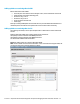
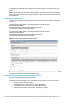
Defining a new vNet via GUI
Create a vNet and name it “vNet-PROD-1”
Login to Virtual Connect, if a Domain has not been created, create it now, but cancel out of
the network and profile wizards.
On the Virtual Connect Manager screen, click Define, Ethernet Network to create a vNet
Ether the Network Name of “vNet-PROD-1”
Note; Do NOT select any of the options (ie; Smart Link, Private Networks etc.)
Select Add Port, then add the following ports;
Enclosure 1, Bay 1, Port 1
Leave Connection Mode as Auto
Select Apply
Create a vNet and name it “vNet-PROD-2”
Login to Virtual Connect, if a Domain has not been created, create it now, but cancel out of
the network and profile wizards.
On the Virtual Connect Manager screen, click Define, Ethernet Network to create a vNet
Ether the Network Name of “vNet-PROD-2”
Note; Do NOT select any of the options (ie; Smart Link, Private Networks etc.)
Select Add Port, then add the following ports;
Enclosure 1, Bay 2, Port 1
Leave Connection Mode as Auto
Select Apply
Note: By connecting ONE Uplink from each vNet we have provided a redundant path to the network.
As each uplink originates from a different VC module and provided connectivity for its own vNet. All
uplinks will be Active. This configuration provides the ability to lose an uplink cable, network switch