
HP Virtual Connect 1Gb Ethernet Cookbook
Scenario 3 – Multiple Simple Networks Providing Redundancy and Link Aggregation 802.3ad (LACP) with VLAN Tunneling
– VMware ESX 39
Installation and configuration
Switch configuration
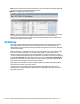
Appendices A and B provide a summary of the commands required to configure the switch in either
a Cisco IOS or a ProCurve network infrastructure. The configuration information provided in the
appendices assumes the following information:
The upstream switch ports are configured as TRUNK ports, presenting VLANs 1, 101-105 and 2101-
2150.
Note: VLAN 101 is set to default (untagged).
The upstream switch ports are configured within the same Link Aggregation Group.
When adding the additional uplinks to the vNet, the switch ports connected to Virtual Connect will
need to be configured for LACP and configured for the same Link Aggregation Group.
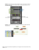
Configuring the VC module
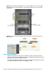
Physically connect Ports 1 and 2 of the first network switch to Ports 1 and 2 on the VC module in
Bay 1.
Physically connect Ports 1 and 2 of the second network switch to Ports 1 and 2 of the VC module in
Bay 2, if you have only one network switch, connect the second VC module cables to alternates port
on the same switch. This will NOT create a network loop and does not require Spanning Tree to be
configured.
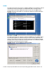
VC CLI commands
Many of the configuration settings within VC can be also be accomplished via a CLI command set. In
order to connect to VC via a CLI, open an SSH connection to the IP address of the active VCM. Once
logged in, VC provides a CLI with help menus. Through this scenario the CLI commands to configure
VC for each setting will also be provided.
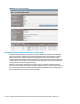
Defining a new vNet via GUI
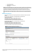
Create a vNet and name it “vNet-PROD-1”
Login to Virtual Connect, if a Domain has not been created, create it now, but cancel out of
the network and profile wizards.
On the Virtual Connect Manager screen, click Define, Ethernet Network to create a vNet
Ether the Network Name of “vNet-PROD-1”
Note; Do NOT select any of the options (ie; Smart Link, Private Networks etc.)
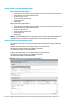
Select Add Port, then add the following ports;
Enclosure 1, Bay 1, Port 1
Enclosure 1, Bay 1, Port 2
Enable Smart Link
Enable VLAN Tunneling
Leave Connection Mode as Auto
Select Apply
Create a vNet and name it “vNet-PROD-2”
Login to Virtual Connect, if a Domain has not been created, create it now, but cancel out of
the network and profile wizards.
On the Virtual Connect Manager screen, click Define, Ethernet Network to create a vNet
Ether the Network Name of “vNet-PROD-2”
Select Add Port, then add the following ports;
Enclosure 1, Bay 2, Port 1
Enclosure 1, Bay 2, Port 2
Enable Smart Link