
HP Virtual Connect 1Gb Ethernet Cookbook


Scenario 3 – Multiple Simple Networks Providing Redundancy and Link Aggregation 802.3ad (LACP) with VLAN Tunneling
– VMware ESX 44
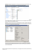
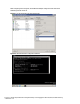
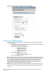
Figure 38 - Both NICs for Profile ESX-1are connected to the network through vNet=PROD-1 and
vNet-PROD-2, VLANs are configured as Port Groups within the virtual switch.
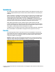
Note: As VLAN 101 is set as untagged at the upstream switch port, the management network port
group should be defined as untagged. This will allow the server to be deployed, without having
the set a VLAN ID for the management network.
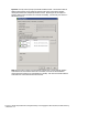
Figure 39 - Configuring the ESX vSwitch for Multiple Networks / VLANs. If additional VLANs need
to be supported, simply configure the upstream switch ports for those VLANs, then configure the
vSwitch as below to support those additional VLANs.
Note: As this Scenario is based on an Active/Active configuration, and Smart Link is enabled,
ensure that the vSwitch Network Failover Detection is set to “Link Status only”. If an uplink or
external switch fails, smart link will turn the server connection off, causing the vSwitch to fail
over to the alternate NIC.