
HP Virtual Connect 1Gb Ethernet Cookbook
Scenario 6 – VLAN Tagging (802.1Q) with Multiple Shared Uplink Sets (SUS) and Link Aggregation using LACP (802.3ad) –
VMware ESX 73
Installation and configuration
Switch configuration
Appendices A and B provide a summary of the commands required to configure the switch in either
a Cisco IOS or a ProCurve network infrastructure. The configuration information provided in the
appendices assumes the following information:
The upstream switch ports are configured as TRUNK ports, presenting VLANs 1, 101-105 and 2101-
2150.
Note: VLAN 101 is set to default (untagged).
The upstream switch ports are configured within the same Link Aggregation Group.
When adding the additional uplinks to the vNet, the switch ports connected to Virtual
Connect will need to be configured for LACP and configured for the same Link Aggregation
Group.
Configuring the VC module
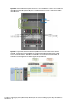
Physically connect Ports 1 and 2 of the first network switch to Ports 1 and 2 on the VC module in
Bay 1.
Physically connect Ports 1 and 2 of the second network switch to Ports 1 and 2 of the VC module in
Bay 2, if you have only one network switch, connect the second VC module cables to alternates port
on the same switch. This will NOT create a network loop and does not require Spanning Tree to be
configured.
VC CLI commands
Many of the configuration settings within VC can also be accomplished via a CLI command set. In order to
connect to VC via a CLI, open an SSH connection to the IP address of the active VCM. Once logged in, VC
provides a CLI with help menus. Through this scenario the CLI commands to configure VC for each setting
will also be provided.
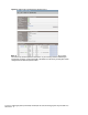
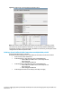
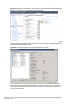
Defining a new Shared Uplink Sets via GUI
Create a SUS and name it “VLAN-Trunk-1”, assign 2 uplinks from the Bay 1 module and add VLANs
1, 101-105, 2101-2150
On the Virtual Connect Manager screen, click Define, Shared Uplink Set to create a SUS
Ether the Network Name of “VLAN-Trunk-1”
Select Add Port, then add the following ports;
Enclosure 1, Bay 1, Port 1
Enclosure 1, Bay 1, Port 2
Add Networks as follows;
VLAN-101, as native VLAN
VLAN-1,101-105 and VLAN-2101-2150
Enable Smartlink for ALL networks
Leave Connection Mode as Auto
Note: By creating a SUS we have provided the ability to present one or many VLANs to a server
NIC. As two uplinks are configured from the module Link Aggregation (802.3ad, LACP) will be
used to ensure both links are active. This configuration provides additional bandwidth and the
ability to lose an uplink cable.
Note: Smart Link – In this configuration Smartlink should be enabled. Smartlink is used to turn
off downlink ports within Virtual Connect network, if ALL available uplinks to that network are
down.