
HP Virtual Connect Fibre Channel Networking Scenarios Cookbook

11
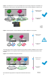
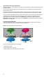
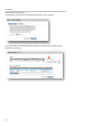
Figure 2: A same SAN Fabric can consist of several SAN switches. In the following configuration, each SAN Fabric has
two SAN switches, and the previous “Participating uplinks must connect to the same SAN fabric” prerequisite is met.
VC Domain
Bay 1
XP
EVA
MSA
12Vdc 12Vdc
HP StorageWorks
4/32B SAN Switch
0 1 2 3 8 9 10 11 16 17 18 19 24 25 26 273130292823222120151413127654
12Vdc 12Vdc
HP StorageWorks
4/32B SAN Switch
0 1 2 3 8 9 10 11 16 17 18 19 24 25 26 273130292823222120151413127654
12Vdc 12Vdc
HP StorageWorks
4/32B SAN Switch
0 1 2 3 8 9 10 11 16 17 18 19 24 25 26 273130292823222120151413127654
12Vdc 12Vdc
HP StorageWorks
4/32B SAN Switch
0 1 2 3 8 9 10 11 16 17 18 19 24 25 26 273130292823222120151413127654
3PAR
Bay 2
VC SAN Fabrics defined
in the VC Domain
External Datacenter
SAN Fabrics
VC SAN A-1
VC SAN B-1
Fabric 1A
Fabric 1B
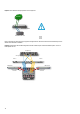
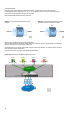
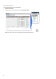
Figure 3: Connecting uplinks of a single VC SAN Fabric to two different SAN fabrics is not supported
VC Domain
Fabric 1A
Fabric 2A
VC-FC Module
VC SAN Fabrics defined
in the VC Domain
External Datacenter
SAN Fabrics
VC Domain
Fabric 1B
Fabric 2B
VC-FC Module
Bay 3
Bay 4
VC SAN A-1
VC SAN B-1
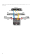
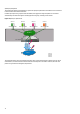
To provide granular control over which server blades use each uplink port, different VC SAN fabrics can be connected
to the same SAN fabric. This configuration enables the distribution of servers according to I/O workloads, as shown
in Figure 3.
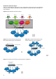
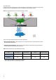
Figure 4: Servers distributed according to I/O workloads
VC Domain
Fabric 1A
VC-FC Module
VC SAN A-1
VC SAN Fabrics defined
in the VC Domain
External Datacenter
SAN Fabrics
VC Domain
VC-FC Module
VC SAN B-1
Bay 3
Bay 4
VC SAN A-2
Fabric 1B
VC SAN B-2
Direct attached Storage Systems are not supported with the Fabric-Attach mode.