
HP Virtual Connect for c-Class BladeSystem Version 4.01 User Guide
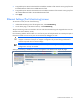
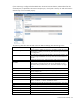
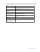
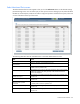
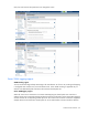
Table Of Contents
- HP Virtual Connect for c-Class BladeSystem Version 4.01 User Guide
- Abstract
- Notice
- Contents
- Introduction
- HP Virtual Connect Manager
- Virtual Connect domains
- Understanding Virtual Connect domains
- Managing domains
- Managing SNMP
- Viewing the system log
- Managing SSL configuration
- HP BladeSystem c-Class enclosures
- Virtual Connect users and roles
- Understanding VC administrative roles
- Managing users
- Local Users screen
- Configuring LDAP, RADIUS, and TACACS+
- Minimum requirements
- LDAP Server Settings (LDAP Server) screen
- LDAP Server Settings (LDAP Groups) screen
- LDAP Server Settings (LDAP Certificate) screen
- RADIUS Settings (RADIUS Server) screen
- RADIUS Settings (RADIUS Groups) screen
- TACACS+ Settings screen
- Role Management (Role Authentication Order) screen
- Role Management (Role Operations) screen
- Virtual Connect networks
- Understanding networks and shared uplink sets
- Managing networks
- Network Access Groups screen
- Define Network Access Group screen
- Ethernet Settings (Port Monitoring) screen
- Ethernet Settings (Advanced Settings) screen
- Quality of Service
- IGMP Settings (IGMP Configuration) screen
- IGMP Settings (Multicast Filter Set) screen
- Define Ethernet Network screen
- Ethernet Networks (External Connections) screen
- Ethernet Networks (Server Connections) screen
- Managing shared uplink sets
- Virtual Connect fabrics
- Virtual Connect server profiles
- Understanding server profiles
- Managing MAC, WWN, and server virtual ID settings
- Managing server profiles
- Define Server Profile screen
- Creating FCoE HBA connections for a BL890c i4
- Limited Ethernet connections when using HP Virtual Connect Flex-10/10D modules
- Creating iSCSI connections
- Flex-10 iSCSI connections
- Define Server Profile screen (multiple enclosures)
- Multiple network connections for a server port
- Defining server VLAN mappings
- Fibre Channel boot parameters
- Server Profiles screen
- Edit Server Profile screen
- Assigning a server profile with FCoE connections to an HP ProLiant BL680c G7 Server Blade
- Unassigning a server profile with FCoE connections to an HP ProLiant BL680c G7 Server Blade and deleting the SAN fabric
- General requirements for adding FC or FCoE connections
- Define Server Profile screen
- Virtual Connect and Insight Control Server Deployment
- Virtual Connect modules
- Firmware updates
- Stacking Links screen
- Throughput Statistics screen
- Enclosure Information screen
- Enclosure Status screen
- Interconnect Bays Status and Summary screen
- Causes for INCOMPATIBLE status
- Ethernet Bay Summary (General Information) screen
- Ethernet Bay Summary (Uplink Port Information) screen
- Ethernet Bay Summary (Server Port Information) screen
- Ethernet Bay Summary (MAC Address Table) screen
- Ethernet Bay Summary (IGMP Multicast Groups) screen
- Ethernet Bay Summary (Name Server) screen
- Ethernet Port Detailed Statistics screen
- FC Port Detailed Statistics screen
- FC Bay Summary screen
- Interconnect Bay Overall Status icon definitions
- Interconnect Bay OA Reported Status icon definitions
- Interconnect Bay VC Status icon definitions
- Interconnect Bay OA Communication Status icon definitions
- Server Bays Summary screen
- Server Bay Status screen
- Port status conditions
- Interconnect module removal and replacement
- Virtual Connect modules
- Upgrading to an HP Virtual Connect 8Gb 24-Port FC Module
- Upgrading to an HP Virtual Connect 8Gb 20-Port FC Module
- Upgrading or removing an HP Virtual Connect Flex-10, HP Virtual Connect FlexFabric, or HP Virtual Connect Flex-10/10D module
- Upgrading to an HP Virtual Connect FlexFabric module from a VC-FC module
- Onboard Administrator modules
- Maintenance and troubleshooting
- Appendix: Using Virtual Connect with nPartitions
- Support and other resources
- Acronyms and abbreviations
- Documentation feedback
- Index
Virtual Connect networks 100
VC provides the ability to monitor server downlink ports for pause flood conditions and take protective action
by disabling the port. The default polling interval is 10 seconds and is not customer configurable. VC
provides system logs and SNMP traps for events related to pause flood detection.
This feature operates at the physical port level. When a pause flood condition is detected on a Flex-10
physical port, all Flex-10 logical ports associated with physical ports are disabled.
When the pause flood protection feature is enabled, this feature detects pause flood conditions on server
downlink ports and disables the port. The port remains disabled until an administrative action is taken. The
administrative action involves the following steps:
1. Resolve the issue with the NIC on the server causing the continuous pause generation.
This might include updating the NIC firmware and device drivers. For information on firmware updates,
see the server support documentation.
Rebooting the server might not clear the pause flood condition if the cause of the pause flood condition
is in the NIC firmware. In this case, the server must be completely disconnected from the power source
to reset the NIC firmware. To perform a server reboot with power disconnection:
a. Shut down the server.
b. Log in to Onboard Administrator with Administrator privileges using the OA CLI.
c. Enter the command reset server x, where [x=bay number].
d. Confirm that you want to reset the server blade.
2. Re-enable the disabled ports on the VC interconnect modules using one of the following methods:
o Click Re-enable Ports in the GUI.
o Use the "reset port-protect" CLI command.
The SNMP agent supports trap generation when a pause flood condition is detected or cleared.
Virtual Connect provides the ability to enable or disable port pause flood protection. The feature is enabled
by default and applies to all VC-Enet modules in the domain. Port pause floods are detected and server ports
can be disabled even prior to any enclosure being imported.
Configuring Throughput Statistics
Telemetry support for network devices caters to seamless operations and interoperability by providing
visibility into what is happening on the network at any given time. It offers extensive and useful detection
capabilities which can be coupled with upstream systems for analysis and trending of observed activity.
The Throughput Statistics configuration determines how often the Throughput Statistics are collected and the
supported time frame for sample collection before overwriting existing samples. When the time frame for
sample collection is reached, the oldest sample is removed to allocate room for the new sample.
Configuration changes can be made without having to enable Throughput Statistics. Applying configuration
changes when Throughput statistics is enabled clears all existing samples.
Some conditions can clear existing Throughput Statistics:
• Disabling the collection of Throughput Statistics clears all existing samples.
• Changing the sampling rate clears all existing samples.
• Power cycling a VC-Enet module clears all Throughput Statistics samples for that module.
Collected samples are available for analysis on the Throughput Statistics screen (on page 226), accessible
by selecting Throughput Statistics from the Tools pull-down menu.
The following table describes the available actions for changing Throughput Statistics settings.