
HP Virtual Connect for c-Class BladeSystem Version 4.01 User Guide
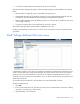
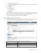
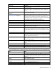
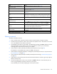
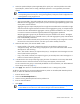
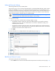
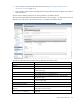
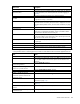
Table Of Contents
- HP Virtual Connect for c-Class BladeSystem Version 4.01 User Guide
- Abstract
- Notice
- Contents
- Introduction
- HP Virtual Connect Manager
- Virtual Connect domains
- Understanding Virtual Connect domains
- Managing domains
- Managing SNMP
- Viewing the system log
- Managing SSL configuration
- HP BladeSystem c-Class enclosures
- Virtual Connect users and roles
- Understanding VC administrative roles
- Managing users
- Local Users screen
- Configuring LDAP, RADIUS, and TACACS+
- Minimum requirements
- LDAP Server Settings (LDAP Server) screen
- LDAP Server Settings (LDAP Groups) screen
- LDAP Server Settings (LDAP Certificate) screen
- RADIUS Settings (RADIUS Server) screen
- RADIUS Settings (RADIUS Groups) screen
- TACACS+ Settings screen
- Role Management (Role Authentication Order) screen
- Role Management (Role Operations) screen
- Virtual Connect networks
- Understanding networks and shared uplink sets
- Managing networks
- Network Access Groups screen
- Define Network Access Group screen
- Ethernet Settings (Port Monitoring) screen
- Ethernet Settings (Advanced Settings) screen
- Quality of Service
- IGMP Settings (IGMP Configuration) screen
- IGMP Settings (Multicast Filter Set) screen
- Define Ethernet Network screen
- Ethernet Networks (External Connections) screen
- Ethernet Networks (Server Connections) screen
- Managing shared uplink sets
- Virtual Connect fabrics
- Virtual Connect server profiles
- Understanding server profiles
- Managing MAC, WWN, and server virtual ID settings
- Managing server profiles
- Define Server Profile screen
- Creating FCoE HBA connections for a BL890c i4
- Limited Ethernet connections when using HP Virtual Connect Flex-10/10D modules
- Creating iSCSI connections
- Flex-10 iSCSI connections
- Define Server Profile screen (multiple enclosures)
- Multiple network connections for a server port
- Defining server VLAN mappings
- Fibre Channel boot parameters
- Server Profiles screen
- Edit Server Profile screen
- Assigning a server profile with FCoE connections to an HP ProLiant BL680c G7 Server Blade
- Unassigning a server profile with FCoE connections to an HP ProLiant BL680c G7 Server Blade and deleting the SAN fabric
- General requirements for adding FC or FCoE connections
- Define Server Profile screen
- Virtual Connect and Insight Control Server Deployment
- Virtual Connect modules
- Firmware updates
- Stacking Links screen
- Throughput Statistics screen
- Enclosure Information screen
- Enclosure Status screen
- Interconnect Bays Status and Summary screen
- Causes for INCOMPATIBLE status
- Ethernet Bay Summary (General Information) screen
- Ethernet Bay Summary (Uplink Port Information) screen
- Ethernet Bay Summary (Server Port Information) screen
- Ethernet Bay Summary (MAC Address Table) screen
- Ethernet Bay Summary (IGMP Multicast Groups) screen
- Ethernet Bay Summary (Name Server) screen
- Ethernet Port Detailed Statistics screen
- FC Port Detailed Statistics screen
- FC Bay Summary screen
- Interconnect Bay Overall Status icon definitions
- Interconnect Bay OA Reported Status icon definitions
- Interconnect Bay VC Status icon definitions
- Interconnect Bay OA Communication Status icon definitions
- Server Bays Summary screen
- Server Bay Status screen
- Port status conditions
- Interconnect module removal and replacement
- Virtual Connect modules
- Upgrading to an HP Virtual Connect 8Gb 24-Port FC Module
- Upgrading to an HP Virtual Connect 8Gb 20-Port FC Module
- Upgrading or removing an HP Virtual Connect Flex-10, HP Virtual Connect FlexFabric, or HP Virtual Connect Flex-10/10D module
- Upgrading to an HP Virtual Connect FlexFabric module from a VC-FC module
- Onboard Administrator modules
- Maintenance and troubleshooting
- Appendix: Using Virtual Connect with nPartitions
- Support and other resources
- Acronyms and abbreviations
- Documentation feedback
- Index

Virtual Connect networks 120
Field name Description
External Uplink Ports
Shared Uplink Set/External VLAN
ID/Native VLAN
These options are only available if there are shared uplink sets defined.
For more information, see “Shared uplink sets and VLAN tagging (on
page 84)."
Port
Network port locations (enclosure, bay, and port numbers)
Port Role
Applicable when Failover Connection Mode is selected. The port can be
designated as Primary or Secondary.
Port Status
Shows the link status, link speed, and connectivity of the port. If the port
is unlinked and no connectivity exists, the cause is displayed. For more
information about possible causes, see "Port status conditions (on page
264)."
Connector Type
Displays the type of connector on the port; for example, RJ-45
Connected To
If the port is connected to a switch that supports LLDP, the switch LLDP
system name or management IP address. A link is provided to obtain
more information about the far-end switch port.
PID
When selected, this option sets/clears the port identifier color as blue on
the VC E-net module to aid in the location of the specific uplink. The PID
status for the overall network also appears.
Speed/Duplex
Pull-down menu to specify the speed and duplex (where applicable) of
the uplink port
Connection Mode
Displays whether connection mode is set to Auto or Failover.
LACP Timer
Displays duration of the LACP timer.
Network Access Groups
Displays the Network Access Groups that include this network.
The following table describes the available actions in the Edit Ethernet Network screen. Clicking another link
in the pull-down menu or left navigation tree causes current edits that have not been applied to be lost.
Task Action
Modify network color
Select a color from the Color pull-down menu.
Modify network label
Type a label in the Labels field, and then press Enter. A network can have
up to 16 labels. Labels cannot contain spaces and are limited to 24
characters.
Enable or disable Smart Link on the
network being defined
Select the Smart Link checkbox.
Designate or do not designate the
network as a private network
Select the Private Network checkbox.
Enable or disable VLAN tunneling
Select the Enable VLAN Tunneling checkbox.
Enable or disable the network
Select the Enabled checkbox.
Set a custom value for preferred link
connection speed or maximum link
connection speed
Select the Advanced Network Settings checkbox.
Set the Connection Mode
Select Auto or Failover. For a description of these modes, see "Defining
a network (on page 116)."
Set the LACP Timer
Select the duration for the LACP Timer ("LACP timer configuration" on
page 101).
Add an external uplink port to the
network
Use the cascading menu to select a port, and then click Add Port.
Change the uplink interface port speed
or disable the port
Click the pull-down box under Speed/Duplex, and then select a setting.