
HP Virtual Connect for c-Class BladeSystem Version 4.01 User Guide
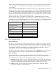

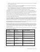
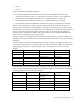
Table Of Contents
- HP Virtual Connect for c-Class BladeSystem Version 4.01 User Guide
- Abstract
- Notice
- Contents
- Introduction
- HP Virtual Connect Manager
- Virtual Connect domains
- Understanding Virtual Connect domains
- Managing domains
- Managing SNMP
- Viewing the system log
- Managing SSL configuration
- HP BladeSystem c-Class enclosures
- Virtual Connect users and roles
- Understanding VC administrative roles
- Managing users
- Local Users screen
- Configuring LDAP, RADIUS, and TACACS+
- Minimum requirements
- LDAP Server Settings (LDAP Server) screen
- LDAP Server Settings (LDAP Groups) screen
- LDAP Server Settings (LDAP Certificate) screen
- RADIUS Settings (RADIUS Server) screen
- RADIUS Settings (RADIUS Groups) screen
- TACACS+ Settings screen
- Role Management (Role Authentication Order) screen
- Role Management (Role Operations) screen
- Virtual Connect networks
- Understanding networks and shared uplink sets
- Managing networks
- Network Access Groups screen
- Define Network Access Group screen
- Ethernet Settings (Port Monitoring) screen
- Ethernet Settings (Advanced Settings) screen
- Quality of Service
- IGMP Settings (IGMP Configuration) screen
- IGMP Settings (Multicast Filter Set) screen
- Define Ethernet Network screen
- Ethernet Networks (External Connections) screen
- Ethernet Networks (Server Connections) screen
- Managing shared uplink sets
- Virtual Connect fabrics
- Virtual Connect server profiles
- Understanding server profiles
- Managing MAC, WWN, and server virtual ID settings
- Managing server profiles
- Define Server Profile screen
- Creating FCoE HBA connections for a BL890c i4
- Limited Ethernet connections when using HP Virtual Connect Flex-10/10D modules
- Creating iSCSI connections
- Flex-10 iSCSI connections
- Define Server Profile screen (multiple enclosures)
- Multiple network connections for a server port
- Defining server VLAN mappings
- Fibre Channel boot parameters
- Server Profiles screen
- Edit Server Profile screen
- Assigning a server profile with FCoE connections to an HP ProLiant BL680c G7 Server Blade
- Unassigning a server profile with FCoE connections to an HP ProLiant BL680c G7 Server Blade and deleting the SAN fabric
- General requirements for adding FC or FCoE connections
- Define Server Profile screen
- Virtual Connect and Insight Control Server Deployment
- Virtual Connect modules
- Firmware updates
- Stacking Links screen
- Throughput Statistics screen
- Enclosure Information screen
- Enclosure Status screen
- Interconnect Bays Status and Summary screen
- Causes for INCOMPATIBLE status
- Ethernet Bay Summary (General Information) screen
- Ethernet Bay Summary (Uplink Port Information) screen
- Ethernet Bay Summary (Server Port Information) screen
- Ethernet Bay Summary (MAC Address Table) screen
- Ethernet Bay Summary (IGMP Multicast Groups) screen
- Ethernet Bay Summary (Name Server) screen
- Ethernet Port Detailed Statistics screen
- FC Port Detailed Statistics screen
- FC Bay Summary screen
- Interconnect Bay Overall Status icon definitions
- Interconnect Bay OA Reported Status icon definitions
- Interconnect Bay VC Status icon definitions
- Interconnect Bay OA Communication Status icon definitions
- Server Bays Summary screen
- Server Bay Status screen
- Port status conditions
- Interconnect module removal and replacement
- Virtual Connect modules
- Upgrading to an HP Virtual Connect 8Gb 24-Port FC Module
- Upgrading to an HP Virtual Connect 8Gb 20-Port FC Module
- Upgrading or removing an HP Virtual Connect Flex-10, HP Virtual Connect FlexFabric, or HP Virtual Connect Flex-10/10D module
- Upgrading to an HP Virtual Connect FlexFabric module from a VC-FC module
- Onboard Administrator modules
- Maintenance and troubleshooting
- Appendix: Using Virtual Connect with nPartitions
- Support and other resources
- Acronyms and abbreviations
- Documentation feedback
- Index

Virtual Connect server profiles 167
• Disable—VC Manager sends a configuration update to the associated mezzanine NIC or embedded
NIC to disable PXE operations.
• Use BIOS—Current BIOS settings are used for embedded NICs and mezzanine NIC PXE operations.
VC Manager makes no changes to the current settings.
This is not applicable to Flex-10 LOM ports when used with Flex-10 interconnect modules. In this
situation, the USE-BIOS option for PXE boot in a VC profile always allows a server to PXE boot from a
LOM port irrespective of the initial LOM settings in the BIOS utility (F9 screen).
HP BladeSystem c-Class server blades have a factory default configuration for PXE to be enabled on
embedded NIC 1 only, included as the last entry in the RBSU IPL priority list (boot order). VC Manager and
the BIOS limit the number of PXE enabled embedded NICs to one. However, additional NIC ports from a
mezzanine adapter can be enabled simultaneously using the "Use BIOS" settings.
All mezzanine NIC ports can be enabled for PXE booting at the same time, along with one embedded NIC
port. If one or more mezzanine NIC ports are enabled for PXE booting, you should review the RBSU IPL list
to validate or update the boot order priority.
If you need to enable PXE on more than one NIC port, you must set all of the NICs' PXE configuration options
in the VCM to "Use BIOS". Then, configure the individual PXE NIC settings using RBSU: F9 during POST to
configure an embedded NIC, and F1 during POST to configure the mezzanine NIC ports. After all of the
selected NIC ports are PXE enabled, you must configure the boot order using the RBSU boot order settings.
Only the first FlexNIC on each physical port of a Flex-10 device can be used for PXE boot. Virtual Connect
cannot enable PXE boot on the remaining FlexNICs of a physical port.
Redundancy for PXE operations can be achieved using multiple PXE enabled NICs. However, the Virtual
Connect Manager is limited to enabling only one NIC for PXE booting. If a configuration requires more than
one NIC to have PXE enabled, you should set all NICs in the VC Manager to the "Use BIOS" setting, and
configure the NIC PXE settings through their respective BIOS utilities (F9 for embedded NICs, and F1 for
mezzanine NIC ports.)
The following table lists examples of valid configurations for PXE enabling NIC ports. This is only a sampling
of the possible valid configurations.
PXE enabled PXE disabled Server blade configuration
Embedded NIC 1,
Mezz 1 NIC port 1
Embedded NIC 2,
Mezz NIC port 2
BL46xc with a dual-port NIC mezzanine
adapter
Embedded NIC 2,
Mezz 1 NIC port 1
Embedded NIC 1,
Mezz NIC port 2
BL46xc with a dual-port NIC mezzanine
adapter
Embedded NIC 1,
Mezz 1 NIC port 1, 2
Embedded NIC 1 BL46xc with a dual-port NIC mezzanine
adapter
Mezz 1 NIC port 1, 2
Embedded NIC 1, 2 BL46xc with a dual-port NIC mezzanine
adapter
Embedded NIC 1,
Mezz 1 NIC port 1
Mezz 2 NIC ports 1, 2
Embedded NIC 2, 3, 4
Mezz 1 NIC port 1
Mezz 2 NIC port 3, 4
BL48xc with a dual-port NIC mezzanine
adapter and a quad-port NIC mezzanine
adapter
Embedded NIC 4,
Mezz 1 NIC ports 1, 2
Mezz 2 NIC ports 1, 2, 3, 4
Embedded NIC 1, 2, 3 BL48xc with a dual-port NIC mezzanine
adapter and a quad-port NIC mezzanine
adapter
Mezz 1 NIC port 1
Mezz 2 NIC ports 1
Embedded NIC 1, 2, 3, 4
Mezz 1 NIC port 2
Mezz 2 NIC port 2, 3, 4
BL48xc with a dual-port NIC mezzanine
adapter and a quad-port NIC mezzanine
adapter