
HP Virtual Connect for c-Class BladeSystem Version 4.01 User Guide
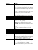
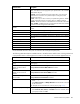
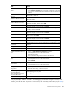
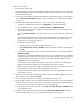
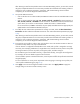
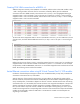
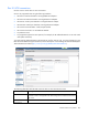
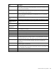
Table Of Contents
- HP Virtual Connect for c-Class BladeSystem Version 4.01 User Guide
- Abstract
- Notice
- Contents
- Introduction
- HP Virtual Connect Manager
- Virtual Connect domains
- Understanding Virtual Connect domains
- Managing domains
- Managing SNMP
- Viewing the system log
- Managing SSL configuration
- HP BladeSystem c-Class enclosures
- Virtual Connect users and roles
- Understanding VC administrative roles
- Managing users
- Local Users screen
- Configuring LDAP, RADIUS, and TACACS+
- Minimum requirements
- LDAP Server Settings (LDAP Server) screen
- LDAP Server Settings (LDAP Groups) screen
- LDAP Server Settings (LDAP Certificate) screen
- RADIUS Settings (RADIUS Server) screen
- RADIUS Settings (RADIUS Groups) screen
- TACACS+ Settings screen
- Role Management (Role Authentication Order) screen
- Role Management (Role Operations) screen
- Virtual Connect networks
- Understanding networks and shared uplink sets
- Managing networks
- Network Access Groups screen
- Define Network Access Group screen
- Ethernet Settings (Port Monitoring) screen
- Ethernet Settings (Advanced Settings) screen
- Quality of Service
- IGMP Settings (IGMP Configuration) screen
- IGMP Settings (Multicast Filter Set) screen
- Define Ethernet Network screen
- Ethernet Networks (External Connections) screen
- Ethernet Networks (Server Connections) screen
- Managing shared uplink sets
- Virtual Connect fabrics
- Virtual Connect server profiles
- Understanding server profiles
- Managing MAC, WWN, and server virtual ID settings
- Managing server profiles
- Define Server Profile screen
- Creating FCoE HBA connections for a BL890c i4
- Limited Ethernet connections when using HP Virtual Connect Flex-10/10D modules
- Creating iSCSI connections
- Flex-10 iSCSI connections
- Define Server Profile screen (multiple enclosures)
- Multiple network connections for a server port
- Defining server VLAN mappings
- Fibre Channel boot parameters
- Server Profiles screen
- Edit Server Profile screen
- Assigning a server profile with FCoE connections to an HP ProLiant BL680c G7 Server Blade
- Unassigning a server profile with FCoE connections to an HP ProLiant BL680c G7 Server Blade and deleting the SAN fabric
- General requirements for adding FC or FCoE connections
- Define Server Profile screen
- Virtual Connect and Insight Control Server Deployment
- Virtual Connect modules
- Firmware updates
- Stacking Links screen
- Throughput Statistics screen
- Enclosure Information screen
- Enclosure Status screen
- Interconnect Bays Status and Summary screen
- Causes for INCOMPATIBLE status
- Ethernet Bay Summary (General Information) screen
- Ethernet Bay Summary (Uplink Port Information) screen
- Ethernet Bay Summary (Server Port Information) screen
- Ethernet Bay Summary (MAC Address Table) screen
- Ethernet Bay Summary (IGMP Multicast Groups) screen
- Ethernet Bay Summary (Name Server) screen
- Ethernet Port Detailed Statistics screen
- FC Port Detailed Statistics screen
- FC Bay Summary screen
- Interconnect Bay Overall Status icon definitions
- Interconnect Bay OA Reported Status icon definitions
- Interconnect Bay VC Status icon definitions
- Interconnect Bay OA Communication Status icon definitions
- Server Bays Summary screen
- Server Bay Status screen
- Port status conditions
- Interconnect module removal and replacement
- Virtual Connect modules
- Upgrading to an HP Virtual Connect 8Gb 24-Port FC Module
- Upgrading to an HP Virtual Connect 8Gb 20-Port FC Module
- Upgrading or removing an HP Virtual Connect Flex-10, HP Virtual Connect FlexFabric, or HP Virtual Connect Flex-10/10D module
- Upgrading to an HP Virtual Connect FlexFabric module from a VC-FC module
- Onboard Administrator modules
- Maintenance and troubleshooting
- Appendix: Using Virtual Connect with nPartitions
- Support and other resources
- Acronyms and abbreviations
- Documentation feedback
- Index
Virtual Connect server profiles 188
Ethernet profile connection Map to bay Map to server port
11
3 Mezz1:1D
12
4 Mezz1:2D
13
1 Not mapped
14
2 Not mapped
FCoE connections for new profiles have changed to the connections shown in the following table.
FCoE profile connection Map to bay Map to server port
1
1 LOM1:1B (FCoE network only)
2
2 LOM1:2B (FCoE network only)
3
3 Mezz1:1B (either FCoE network or SAN Fabric)
4
4 Mezz1:2B (either FCoE network or SAN Fabric)
After upgrading from versions previous to VC v4.01, it is not possible to create an identical profile to the one
created prior to the upgrade. This is because mapping of the FCoE connections changed with the
introduction of the support for dual-hop FCoE on the Flex-10/10D modules. In addition, a FlexNIC-b may no
longer be available as an Ethernet connection if an FCoE connection is also preferred on the same profile.
Creating iSCSI connections
In order to provision iSCSI connections, you must remove any FCoE connections assigned by default when
FlexFabric modules are present in an enclosure. If you are not going to configure FCoE connections and the
adapter does not support iSCSI and FCoE on different PFs, delete the default connections so that those port
functions are available for iSCSI.
In the iSCSI HBA Connections section, add an iSCSI connection. Select a VC network, and then select a boot
setting:
• Disabled—Only iSCSI offload is available. Boot is unavailable.
• Primary—Enables you to set up a fault-tolerant boot path and displays the screen for Flex-10 iSCSI
connections (on page 189). If Primary is already configured, this setting changes to Secondary.
• USE-BIOS—Indicates if boot will be enabled or disabled using the server iSCSI BIOS utility.
The multiple network feature is not supported for iSCSI connections.
VCM looks at the number and types of connections in the profile—FCoE, iSCSI, and Ethernet. FCoE
connections are assigned first, followed by iSCSI and then by Ethernet. It is possible that some connections
will be unmapped. On server boot, the adapter enumerates functions configured by VCM. Any personality
change triggers a server reboot during POST.
After creating the iSCSI offload connections, use the iSCSI BIOS utility or OS tools to configure all iSCSI
parameters.
IMPORTANT:
After a profile has been created with iSCSI offload and assigned to a server, this
iSCSI offload configuration remains until it is manually removed through the system BIOS or OS
utility, even if the iSCSI offload is removed from the profile. Additionally, if iSCSI targets are
added using the system BIOS or the OS utility, those targets remain until they are manually
removed.