
HP Virtual Connect for c-Class BladeSystem Version 4.01 User Guide
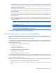

Table Of Contents
- HP Virtual Connect for c-Class BladeSystem Version 4.01 User Guide
- Abstract
- Notice
- Contents
- Introduction
- HP Virtual Connect Manager
- Virtual Connect domains
- Understanding Virtual Connect domains
- Managing domains
- Managing SNMP
- Viewing the system log
- Managing SSL configuration
- HP BladeSystem c-Class enclosures
- Virtual Connect users and roles
- Understanding VC administrative roles
- Managing users
- Local Users screen
- Configuring LDAP, RADIUS, and TACACS+
- Minimum requirements
- LDAP Server Settings (LDAP Server) screen
- LDAP Server Settings (LDAP Groups) screen
- LDAP Server Settings (LDAP Certificate) screen
- RADIUS Settings (RADIUS Server) screen
- RADIUS Settings (RADIUS Groups) screen
- TACACS+ Settings screen
- Role Management (Role Authentication Order) screen
- Role Management (Role Operations) screen
- Virtual Connect networks
- Understanding networks and shared uplink sets
- Managing networks
- Network Access Groups screen
- Define Network Access Group screen
- Ethernet Settings (Port Monitoring) screen
- Ethernet Settings (Advanced Settings) screen
- Quality of Service
- IGMP Settings (IGMP Configuration) screen
- IGMP Settings (Multicast Filter Set) screen
- Define Ethernet Network screen
- Ethernet Networks (External Connections) screen
- Ethernet Networks (Server Connections) screen
- Managing shared uplink sets
- Virtual Connect fabrics
- Virtual Connect server profiles
- Understanding server profiles
- Managing MAC, WWN, and server virtual ID settings
- Managing server profiles
- Define Server Profile screen
- Creating FCoE HBA connections for a BL890c i4
- Limited Ethernet connections when using HP Virtual Connect Flex-10/10D modules
- Creating iSCSI connections
- Flex-10 iSCSI connections
- Define Server Profile screen (multiple enclosures)
- Multiple network connections for a server port
- Defining server VLAN mappings
- Fibre Channel boot parameters
- Server Profiles screen
- Edit Server Profile screen
- Assigning a server profile with FCoE connections to an HP ProLiant BL680c G7 Server Blade
- Unassigning a server profile with FCoE connections to an HP ProLiant BL680c G7 Server Blade and deleting the SAN fabric
- General requirements for adding FC or FCoE connections
- Define Server Profile screen
- Virtual Connect and Insight Control Server Deployment
- Virtual Connect modules
- Firmware updates
- Stacking Links screen
- Throughput Statistics screen
- Enclosure Information screen
- Enclosure Status screen
- Interconnect Bays Status and Summary screen
- Causes for INCOMPATIBLE status
- Ethernet Bay Summary (General Information) screen
- Ethernet Bay Summary (Uplink Port Information) screen
- Ethernet Bay Summary (Server Port Information) screen
- Ethernet Bay Summary (MAC Address Table) screen
- Ethernet Bay Summary (IGMP Multicast Groups) screen
- Ethernet Bay Summary (Name Server) screen
- Ethernet Port Detailed Statistics screen
- FC Port Detailed Statistics screen
- FC Bay Summary screen
- Interconnect Bay Overall Status icon definitions
- Interconnect Bay OA Reported Status icon definitions
- Interconnect Bay VC Status icon definitions
- Interconnect Bay OA Communication Status icon definitions
- Server Bays Summary screen
- Server Bay Status screen
- Port status conditions
- Interconnect module removal and replacement
- Virtual Connect modules
- Upgrading to an HP Virtual Connect 8Gb 24-Port FC Module
- Upgrading to an HP Virtual Connect 8Gb 20-Port FC Module
- Upgrading or removing an HP Virtual Connect Flex-10, HP Virtual Connect FlexFabric, or HP Virtual Connect Flex-10/10D module
- Upgrading to an HP Virtual Connect FlexFabric module from a VC-FC module
- Onboard Administrator modules
- Maintenance and troubleshooting
- Appendix: Using Virtual Connect with nPartitions
- Support and other resources
- Acronyms and abbreviations
- Documentation feedback
- Index
Appendix: Using Virtual Connect with nPartitions 278
iLO controls the blade link to change the configuration of nPars in the blade link domain, and the information
about the new configuration is communicated through the OA to VCM. During the process, VCM:
• Removes profile connections from affected nPars
• Updates its nPar configuration information
• Applies profiles to the new or modified nPars
Assigning a VC profile to an nPar
When an i4 server is configured with multiple nPartitions, each nPartition must be assigned its own profile.
Just as is done with multi-blade servers, a profile assigned to a multi-blade nPar is actually assigned to the
monarch bay of the nPar (and just like with multi-blade servers, the monarch bay in an nPar is the lowest
numbered bay in the nPar).
Mapping profile connections
Profile connections are mapped to an nPar exactly like they are mapped to servers: a 1-blade nPar is handled
exactly like a 1-blade server, and a 2-blade nPar is handled exactly like a 2-blade server.
Reconfiguring nPars
When a blade domain is reconfigured, any profile that is assigned to the monarch bay of any new partition
gets applied to all of the blades in the partition (just like applying a profile to a multi-blade server applies the
profile to all of the blades in the multi-blade server).
The following examples illustrate the events that accompany a reconfiguration. In these examples, assume
that there is a profile assigned to each of four bays.
Example 1: Reconfiguration from AAAA to AACD
The current profile assigned to the first bay is applied to the AAAA partition, and the other profiles (assigned
to the second, third and fourth bays) are considered to be assigned to covered bays and will not have been
used. VCM shows such a profile as assigned to a "Covered - Auxiliary" bay.
When the reconfiguration is done, the OA first generates blade remove events for all four blades in the
AAAA partition, resulting in VCM treating the AAAA partition as having been removed. Then the OA
generates blade add events for the first two blades that identify those two blades as belonging to one
partition (the AA partition), a blade add event for the third blade that identifies it as a single-blade partition
(the C partition), and likewise for the fourth blade (the D partition).
The profile assigned to the first bay is now shown as assigned to the AA partition and is applied to the first
two blades. The profile assigned to the second blade is shown as covered and is not used. The profile
assigned to the third bay is now shown as assigned to the C partition and is applied to that blade, and
likewise the profile assigned to the fourth bay is shown as assigned to the D partition and is applied to that
blade.
Example 2: Reconfiguration from AACD to ABCD
The current profile assigned to the first bay is applied to the AA partition, the profile assigned to the second
bay is covered and not used, the profile assigned to the third bay is applied to the C partition, and the profile
assigned to the fourth bay is applied to the D partition.