
HP Virtual Connect for c-Class BladeSystem Version 4.01 User Guide
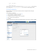
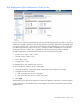
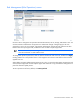
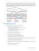
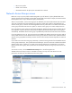
Table Of Contents
- HP Virtual Connect for c-Class BladeSystem Version 4.01 User Guide
- Abstract
- Notice
- Contents
- Introduction
- HP Virtual Connect Manager
- Virtual Connect domains
- Understanding Virtual Connect domains
- Managing domains
- Managing SNMP
- Viewing the system log
- Managing SSL configuration
- HP BladeSystem c-Class enclosures
- Virtual Connect users and roles
- Understanding VC administrative roles
- Managing users
- Local Users screen
- Configuring LDAP, RADIUS, and TACACS+
- Minimum requirements
- LDAP Server Settings (LDAP Server) screen
- LDAP Server Settings (LDAP Groups) screen
- LDAP Server Settings (LDAP Certificate) screen
- RADIUS Settings (RADIUS Server) screen
- RADIUS Settings (RADIUS Groups) screen
- TACACS+ Settings screen
- Role Management (Role Authentication Order) screen
- Role Management (Role Operations) screen
- Virtual Connect networks
- Understanding networks and shared uplink sets
- Managing networks
- Network Access Groups screen
- Define Network Access Group screen
- Ethernet Settings (Port Monitoring) screen
- Ethernet Settings (Advanced Settings) screen
- Quality of Service
- IGMP Settings (IGMP Configuration) screen
- IGMP Settings (Multicast Filter Set) screen
- Define Ethernet Network screen
- Ethernet Networks (External Connections) screen
- Ethernet Networks (Server Connections) screen
- Managing shared uplink sets
- Virtual Connect fabrics
- Virtual Connect server profiles
- Understanding server profiles
- Managing MAC, WWN, and server virtual ID settings
- Managing server profiles
- Define Server Profile screen
- Creating FCoE HBA connections for a BL890c i4
- Limited Ethernet connections when using HP Virtual Connect Flex-10/10D modules
- Creating iSCSI connections
- Flex-10 iSCSI connections
- Define Server Profile screen (multiple enclosures)
- Multiple network connections for a server port
- Defining server VLAN mappings
- Fibre Channel boot parameters
- Server Profiles screen
- Edit Server Profile screen
- Assigning a server profile with FCoE connections to an HP ProLiant BL680c G7 Server Blade
- Unassigning a server profile with FCoE connections to an HP ProLiant BL680c G7 Server Blade and deleting the SAN fabric
- General requirements for adding FC or FCoE connections
- Define Server Profile screen
- Virtual Connect and Insight Control Server Deployment
- Virtual Connect modules
- Firmware updates
- Stacking Links screen
- Throughput Statistics screen
- Enclosure Information screen
- Enclosure Status screen
- Interconnect Bays Status and Summary screen
- Causes for INCOMPATIBLE status
- Ethernet Bay Summary (General Information) screen
- Ethernet Bay Summary (Uplink Port Information) screen
- Ethernet Bay Summary (Server Port Information) screen
- Ethernet Bay Summary (MAC Address Table) screen
- Ethernet Bay Summary (IGMP Multicast Groups) screen
- Ethernet Bay Summary (Name Server) screen
- Ethernet Port Detailed Statistics screen
- FC Port Detailed Statistics screen
- FC Bay Summary screen
- Interconnect Bay Overall Status icon definitions
- Interconnect Bay OA Reported Status icon definitions
- Interconnect Bay VC Status icon definitions
- Interconnect Bay OA Communication Status icon definitions
- Server Bays Summary screen
- Server Bay Status screen
- Port status conditions
- Interconnect module removal and replacement
- Virtual Connect modules
- Upgrading to an HP Virtual Connect 8Gb 24-Port FC Module
- Upgrading to an HP Virtual Connect 8Gb 20-Port FC Module
- Upgrading or removing an HP Virtual Connect Flex-10, HP Virtual Connect FlexFabric, or HP Virtual Connect Flex-10/10D module
- Upgrading to an HP Virtual Connect FlexFabric module from a VC-FC module
- Onboard Administrator modules
- Maintenance and troubleshooting
- Appendix: Using Virtual Connect with nPartitions
- Support and other resources
- Acronyms and abbreviations
- Documentation feedback
- Index
Virtual Connect networks 90
o
On the Alphabetical tab, click a letter to show only network names that begin with that group of
letters, or click All to show all networks alphabetically.
o On the Filtered tab, use the pull-down menus to define the filter criteria, and then click Go.
3. Drag and drop the networks that should be included as members of the network access group from the
Excluded Networks field to the Included Networks field.
4. Click Apply.
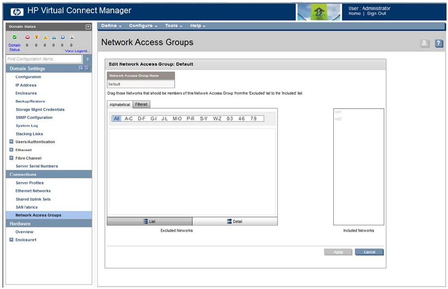
Edit Network Access Group screen
To access this screen:
• Click the Edit link for a network access group on the Network Access Groups screen (on page 88).
• Enter a network access group name in the Find Configuration Items search field in the left navigation
tree, and then select the network access group.
Use this screen to edit the properties of an existing Network Access Group.
This screen can only be edited by users with network role permissions, but it is viewable by all authorized
users.
To edit a network access group:
1. Enter a new name for the network access group in the Network Access Group Name field. The name
can consist of up to 64 alphanumeric characters, including the hyphen (-), underscore (_), and period
(.). You cannot rename the Default network access group.
2. To filter the list of available networks, do one of the following:
o On the Alphabetical tab, click a letter to show only network names that begin with that group of
letters, or click All to show all networks alphabetically.
o On the Filtered tab, use the pull-down menus to define the filter criteria, and then click Go.