Technical white paper Virtual Connect Multi-Enclosure Stacking Reference Guide Table of contents Executive Summary 2 Multi-Enclosure Stacking Guidelines 2 When to choose Multi-Enclosure Stacking 3 Virtual Connect Domain Stack Planning Virtual Connect Fibre Channel 4 9 Multi-Enclosure Stacking External Connection Architectures 10 Consolidating Existing VC Domains and Enclosures 18 Removing an enclosure from a multienclosure domain 18 For more information 20
Executive Summary Customers today are challenged with simplifying the network edge by reducing complexity and cost. HP’s Virtual Connect solution helps customers simplify server network connections by cleanly separating the server enclosure from the data center network. Stacking multiple enclosures enables the management of up to four enclosures from a single control point.
The first Virtual Connect domain created on the first enclosure will become the Base Enclosure. Remote Enclosures will then be imported into the Base Enclosure Virtual Connect Domain. The base enclosure will contain the primary and secondary Virtual Connect Manager instances. The base enclosure “role” cannot be transferred to another enclosure in the stack.
Conversely, here are some reasons why you could not or would not want to use Multi-Enclosure Stacking: If you are using c3000 enclosures If the enclosure you are considering to be the base enclosure has Virtual Connect 1/10Gb modules running Virtual Connect Manager If you want to maintain different VC firmware versions across the enclosures If not all OA and VC modules are on the same network/IP subnet If many VC faceplate ports are used for uplinks and you do not have enough available port
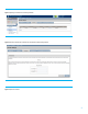
Figure 1: Importing an enclosure into an existing VC Domain Figure 2: Enter the IP address and credentials of for the OA of the enclosure being imported.
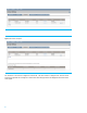
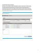
Figure 4: The enclosure is imported The enclosures in the stack are assigned an enclosure ID. The base enclosure is assigned enc0, and the remote enclosures are given IDs enc1 through enc3. The Enclosure name being imported is also displayed in the second column of the graphic.
Figure 5: VC Domain Stacking Links After successful configuration of the ME Stack, you will be able to create a VC network and choose any uplink port in the VC domain. A profile can be assigned to any server blade bay within any enclosure in the Virtual Connect domain.
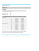
Figure 6: Virtual Connect network creation Figure 7: Blade server profile placement 8
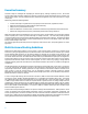
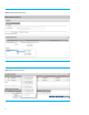
Virtual Connect Fibre Channel When VC FC, VC Flex-10/10D or VC FlexFabric is implemented in a multi-enclosure domain, all enclosures must have identical VC-FC, VC Flex-10/10D and VC FlexFabric module placement and FC or FCoE cabling. VC-FC does not support the concept of Multi-Enclosure stacking. When a VC Fibre Channel (FC) Fabric is created, its configuration is automatically replicated to the remote enclosures.
Figure 9: Example of VC FC stacking configuration Multi-Enclosure Stacking External Connection Architectures This section will outline multiple scenarios for stacking 2, 3 and 4 enclosures to form a Multi-Enclosure Stack. Each example displayed is configured with 4 uplink ports which connect to the external switches. The Virtual Connect network would be created with an A and B side to allow all links to be in an active state.
Modules (including FlexFabric Modules) must be interconnected via stacking links. It is also highly recommended to have at least one level of redundancy in the stacking links, meaning that you could lose any one stacking cable and still have connectivity from any VC Ethernet module to any other VC Ethernet module in the domain over the remaining stacking links.
When the modules on the left-hand side (the odd side) of enc1 and enc2 reboot to activate the new firmware, the servers in enc1 and enc2 would be isolated from enc0 and would lose network connectivity through the enc0 uplinks. It is still possible and supported to use such a topology if you are willing to incur this connectivity loss during a firmware upgrade or if you are willing to use the command-line options of VCSU to change the order in which the modules are rebooted to activate the new firmware.
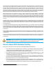
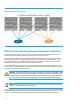
Dual Ring 2 Enclosures Note that uplinks are connected to alternate enclosures/VC modules (left side/right side). In addition to the external stacking cables (red lines) seen in the following graphic, the VC modules are also cross connected internally, creating a L2 ring topology within Virtual Connect. This configuration provides the ability to sustain a chassis, module, uplink or upstream switch failure/outage and still maintain connectivity to the network.
Dual Ring 3 Enclosures Note that uplinks are connected to alternate enclosures/VC modules (left side/right side). In addition to the external stacking cables (red lines) seen in the following graphic, the VC modules are also cross connected internally, creating a L2 ring topology within Virtual Connect. Communications from Enclosure 3 would be routed through either enclosure 1 or two, depending on how the VC networks are assigned to the server profiles.
Dual Ring 4 Enclosures Note that uplinks are connected to alternate enclosures/VC modules (left side/right side). In addition to the external stacking cables (red lines) seen in the following graphic, the VC modules are also cross connected internally, creating a L2 ring topology within Virtual Connect. Communications from Enclosure 3 and 4 would be routed through either enclosure 1 or two, depending on how the VC networks are assigned to the server profiles.
Additional stacking cables may be required or desired for some of the following reasons: If you have more than two VC-Enet modules per enclosure. If you want redundancy for more than one cable or module failure. If you want to minimize latency between a NIC and its uplink by reducing the hop count. If you want to increase bandwidth for IP communication between enclosures Any of these reasons may lead you to add more physical connections in your stacking environment.
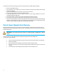
Base Enclosure Enclosure ID enc0 Uplink Ports FAN 1 FAN 5 SHARED: UPLINK or X-LINK HP VC Flex-10 Enet Module 1 UID 3 UID X1 X2 X3 X4 X5 X6 X1 X2 X3 X4 X5 X6 X7 SHARED: UPLINK or X-LINK HP VC Flex-10 Enet Module X8 X1 X2 X3 X4 X5 X6 X1 X2 X3 X4 X5 X6 X7 X8 2 UID X1 X1 SHARED SHARED SHARED: UPLINK or X-LINK HP VC Flex-10 Enet Module X7 SHARED: UPLINK or X-LINK HP VC Flex-10 Enet Module X8 X7 X8 4 UID X1 X1 SHARED SHARED 6 5 8 7 Enclosure Interlink
It is customary to put uplink cables on the top-most and bottom-most enclosures as shown in most of the example pictures above. You can also put uplink cables on the first and second enclosures as shown in the 3-enclosure example picture.
For more information www.hp.com/go/bladesystems Get connected hp.com/go/getconnected Current HP driver, support, and security alerts delivered directly to your desktop © Copyright 2013 Hewlett-Packard Development Company, L.P. The information contained herein is subject to change without notice. The only warranties for HP products and services are set forth in the express warranty statements accompanying such products and services. Nothing herein should be construed as constituting an additional warranty.