
Converged networks with Fibre Channel over Ethernet and Data Center Bridging
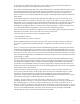
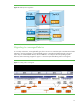
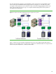
Table Of Contents
13
use QCN in conjunction with PFC to provide lossless operation with smooth congestion management across
large DCB-enabled networks.
QCN uses a special new tag that allows sources of traffic, for example CNAs, to identify traffic flows to all
interconnect devices in a QCN-enabled DCB network. QCN defines two specific points in a network that
implement the QCN protocol, congestion points and reaction points. The QCN protocol has these basic
procedural elements:
• Reaction points initiate traffic into the network. They can include CNAs, target nodes, or DCB-enabled
switches that bridge between native FC networks and the DCB-enabled Ethernet network. Reaction points
tag their frames with traffic flow information identifying the source and destination of the traffic flow.
• When transmit queues fill up due to congestion from oversubscription, congestion points (typically
switches) statistically sample the frames in the congested transmit queues to identify the traffic flows
contributing most to the congestion.
• The congestion point device calculates congestion feedback quanta for each traffic source sampled. The
device uses information from the sampled traffic flow tags to send congestion notifications back to the
traffic sources.
• Upon receiving the congestion notification, a reaction point will use the feedback quanta to reduce the
transmission rate for that traffic flow to that specific destination. QCN does not affect traffic sent on
unrelated flows to unrelated destinations.
• If a reaction point receives no further congestion notification messages, it slowly increases its transmit
rates until they reach normal levels.
Most DCB-enabled Ethernet switches will implement congestion points.
We can roughly equate QCN operation to the TCP window algorithms that restrict traffic flow when the
device detects lost frames. In the case of QCN, however, the protocol operates at layer 2 in the network. It
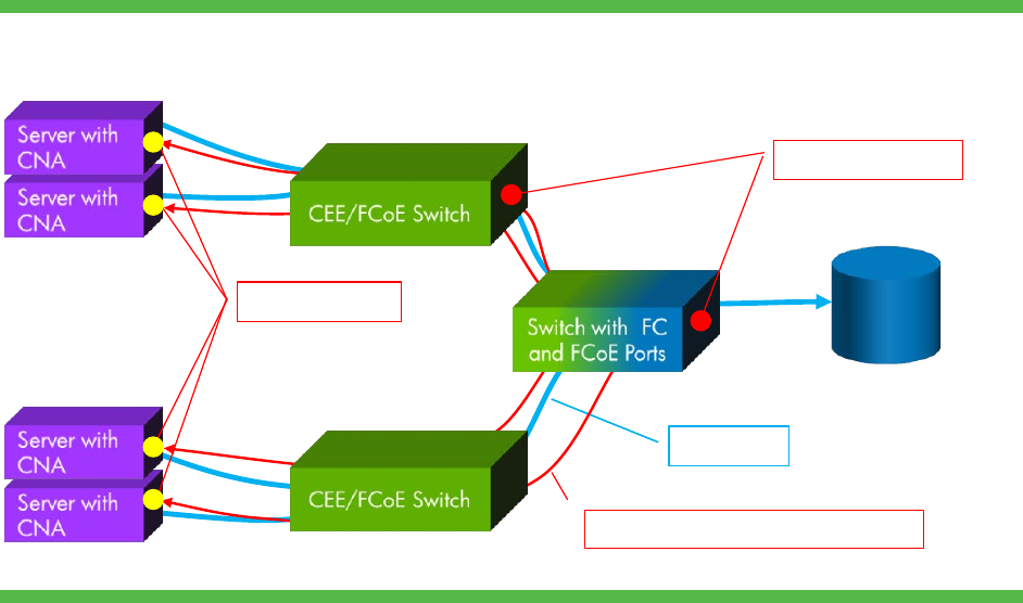
uses high-performance, low-level hardware to improve the network’s ability to react to congestion. Figure 8
illustrates a multi-hop network that implements QCN.
Figure 8. QCN congestion notification
Storage
Reaction Points
Data Flow
Congestion Notification Messages
Congestion Points
In this example, multiple CNAs in servers are sending write data to a common storage device through a
multi-hop network. As a switch queue fills and surpasses a high water mark, the device sends congestion