HP Virtual Connect for c-Class BladeSystem Setup and Installation Guide Version 4.20 Abstract This document contains setup, installation, and configuration information for HP Virtual Connect. This document is for the person who installs, administers, and troubleshoots servers and storage systems. HP assumes you are qualified in the servicing of computer equipment and trained in recognizing hazards in products with hazardous energy levels.
© Copyright 2014 Hewlett-Packard Development Company, L.P. The information contained herein is subject to change without notice. The only warranties for HP products and services are set forth in the express warranty statements accompanying such products and services. Nothing herein should be construed as constituting an additional warranty. HP shall not be liable for technical or editorial errors or omissions contained herein. Microsoft® and Windows® are U.S. registered trademarks of Microsoft Corporation.
Contents Documentation resources ............................................................................................................... 6 Virtual Connect documentation.................................................................................................................... 6 Planning the installation ................................................................................................................. 8 Virtual Connect overview..................................................
Virtual Connect and Insight Control Server Deployment ................................................................................ 55 Accessing HP Virtual Connect Manager ..................................................................................................... 55 Command Line Interface overview ................................................................................................... 56 Logging on to the HP Virtual Connect Manager GUI ................................................
Electrostatic discharge ............................................................................................................... 128 Preventing electrostatic discharge ............................................................................................................ 128 Grounding methods to prevent electrostatic discharge ................................................................................ 128 Support and other resources .........................................................
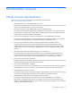
Documentation resources Virtual Connect documentation The following Virtual Connect documentation is available on the HP website (http://www.hp.com/go/vc/manuals): • HP Virtual Connect for c-Class BladeSystem User Guide This guide provides details for the Virtual Connect GUI, including descriptions of screen contents and steps to set up domains, profiles, networks, and storage.
• Release Notes Release notes document new features, resolved issues, known issues, and important notes for each release of the Virtual Connect product and support utility. The HP Virtual Connection Migration Guide technical white paper on the HP website (http://h20564.www2.hp.
Planning the installation Virtual Connect overview HP Virtual Connect is a set of interconnect modules and embedded software for HP BladeSystem c-Class enclosures.
507017-B21, 507019-B21, 681840-B21, 681842-B21 and 681844-B21. For information on updated SKUs, see the QuickSpecs on the HP website (http://www.hp.com/go/productbulletin). VC-Enet modules enable connectivity to data center Ethernet switches. VC-Enet modules can also be directly connected to other types of devices, such as printers, laptops, rack servers, and network storage devices. The VC-FC and FlexFabric modules enable connectivity of the enclosure to data center FC switches.
Using multiple enclosures Multiple enclosure support enables up to four c7000 enclosures to be managed within a single Virtual Connect domain for a total of 128 servers, if double-dense support is enabled while using the Domain Setup Wizard. There are 16 half-height or 8 full-height server bays in a c7000 enclosure. A combination of full-height and half-height servers can be used in the same enclosure. Multiple enclosure domains are not supported on c3000 enclosures.
• • Determine the Ethernet stacking cable layout, and ensure that the proper cable and transceiver options are ordered. Stacking cables enable any Ethernet NIC from any server to be connected to any of the Ethernet networks defined for the enclosure. o For information on cable layout, see "Recommended stacking connections (on page 23)." o For information on supported cable and transceiver options, see the Virtual Connect module QuickSpecs on the HP website (http://www.hp.com/go/vc/manuals).
3. Install stacking links ("Recommended stacking connections" on page 23). 4. Connect the VC-Enet module uplinks to data center networks. The network administrator should have already installed the network cables into the rack with the proper labels. See "Connecting Virtual Connect Ethernet module uplinks (on page 42)." 5. Connect data center FC fabric links (if applicable). 6.
must support dynamic creation of link aggregation groups using the IEEE 802.3ad LACP. All stacking links are disabled. This default configuration enables connectivity testing between server NICs and devices outside the enclosure prior to Virtual Connect domain configuration. When not part of a Virtual Connect domain, all of the VC-FC Module uplink ports are grouped into an uplink port group and dynamically distribute connectivity from all server blades across all available uplink ports.
A server profile can be assigned and defined for each device bay so that the server blade can be powered on and connected to a deployment network. These profiles can then later be modified or replaced by another server profile. A server profile can also be assigned to an empty bay to enable deployment at a later date.
Installation Installation requirements CAUTION: Always use blanks to fill empty spaces in enclosures. This arrangement ensures proper airflow. Using an enclosure without the proper blanks results in improper cooling that can lead to thermal damage. Observe the following requirements: • In all Virtual Connect configurations, a VC-Enet or FlexFabric module must be installed in the enclosure. The embedded VCM operates on this module.
• For the most up-to-date support information, see the HP website (http://www.hp.com/storage/spock). Simple registration is required. • For more information on the association between the server blade mezzanine connectors and the interconnect bays, see the HP BladeSystem enclosure setup and installation guide that ships with the enclosure. During server blade installation, the location of the mezzanine card determines the installation location of the interconnect modules.
In the following tables, "Other" indicates any c-Class interconnect module including a VC, Pass-Thru, or switch.
[Bay 7] Other/empty [Bay 8] Other/empty [Bay 1] VC Ethernet [Bay 2] VC Ethernet [Bay 3] VC Ethernet [Bay 4] VC Ethernet [Bay 5] VC Ethernet [Bay 6] VC Ethernet [Bay 7] Other/empty [Bay 8] Other/empty [Bay 1] VC Ethernet [Bay 2] Empty [Bay 3] VC-FC [Bay 4] Empty [Bay 5] Other/empty [Bay 6] Other/empty [Bay 7] Other/empty [Bay 8] Other/empty [Bay 1] VC Ethernet [Bay 2] VC Ethernet [Bay 3] VC-FC [Bay 4] VC-FC [Bay 5] Other/empty [Bay 6] Other/empty [Bay 7] Other
[Bay 3] VC Ethernet [Bay 4] VC Ethernet [Bay 5] VC Ethernet [Bay 6] VC Ethernet VC Ethernet [Bay 8] VC Ethernet [Bay 7] Bay configuration requirements Primary and backup VC modules Observe the following requirements when installing primary and backup interconnect modules: • Plan your installation carefully. After the VC domain has been created, the position and type of the primary and backup VC modules cannot be changed without deleting and recreating the domain.
• To avoid connectivity loss, do not install VC and non-VC modules in interconnect bays connected to the same server blade mezzanine card. Non-VC modules cannot be installed in an interconnect bay adjacent to a VC module. • Do not mix VC-Enet modules and VC-FC modules in interconnect bays connected to the same server blade mezzanine card. This action generates an enclosure electronic keying error.
• Only install HP Virtual Connect Flex-10 Modules into bays horizontally adjacent to bays containing another HP Virtual Connect Flex-10 Module. If any other type of module is installed, the second one discovered is set to UNKNOWN, and no connections are made to the server NICs attached to the interconnect bay. The module is set to UNKNOWN because it is removed automatically from the VC domain when removed physically from the interconnect bay.
HP Virtual Connect FlexFabric 10Gb/24-port Module requirements The following requirements apply to the installation or replacement of HP Virtual Connect FlexFabric 10Gb/24-port Modules: • For full storage network compatibility, each server blade attached to the HP VC FlexFabric 10Gb/24-port Module must have either an embedded or mezzanine-based FlexFabric converged network adapter.
For information on using IPv6 with Virtual Connect, see the HP Virtual Connect for c-Class BladeSystem User Guide on the HP website (http://www.hp.com/go/vc/manuals). Because Virtual Connect communicates with other components through the Onboard Administrator, special considerations are required when using EBIPA with Virtual Connect Ethernet modules: • The Onboard Administrator must be on the same IP subnet as all Virtual Connect modules.
Single enclosure stacking diagram Modules (top to bottom) HP Virtual Connect FlexFabric-20/40 F8 Modules Stacking four modules • • • • • • HP Virtual Connect FlexFabric 10Gb/24-port Modules HP Virtual Connect FlexFabric 10Gb/24-port Modules HP Virtual Connect FlexFabric 10Gb/24-port Modules HP Virtual Connect Flex-10 10Gb Ethernet Modules HP Virtual Connect FlexFabric 10Gb/24-port Modules HP Virtual Connect FlexFabric-20/40 F8 Modules Stacking six modules • • • HP Virtual Connect FlexFabric 10
Single enclosure stacking diagram Modules (top to bottom) • • • • • • • • • HP Virtual Connect FlexFabric 10Gb/24-port Modules HP Virtual Connect FlexFabric 10Gb/24-port Modules HP Virtual Connect Flex-10 10Gb Ethernet Modules HP Virtual Connect FlexFabric 10Gb/24-port Modules HP Virtual Connect Flex-10 10Gb Ethernet Modules HP Virtual Connect Flex-10/10D Modules HP Virtual Connect FlexFabric 10Gb/24-port Modules HP Virtual Connect FlexFabric 10Gb/24-port Modules HP Virtual Connect FlexFabric-20/4
Single enclosure stacking diagram Modules (top to bottom) • • • • • • • • HP Virtual Connect FlexFabric 10Gb/24-port Modules HP Virtual Connect FlexFabric 10Gb/24-port Modules HP Virtual Connect Flex-10 10Gb Ethernet Modules HP Virtual Connect Flex-10 10Gb Ethernet Modules HP Virtual Connect FlexFabric 10Gb/24-port Modules HP Virtual Connect FlexFabric 10Gb/24-port Modules HP Virtual Connect Flex-10 10Gb Ethernet Modules HP Virtual Connect FlexFabric-20/40 F8 Modules The 1000BASE-T links can be used
• One active link—A VC uplink set can include multiple uplink ports. To prevent a loop with broadcast traffic coming in one uplink and going out another, only one uplink or uplink LAG is active at a time. The uplink or LAG with the greatest bandwidth should be selected as the active uplink. If the active uplink loses the link, then the next best uplink is made active.
Connecting multiple enclosures Virtual Connect supports the connection of up to four c7000 enclosures, which can reduce the number of network connections per rack and also enables a single VC Manager to control multiple enclosures. A single set of cables can be used to carry all external Ethernet traffic from a single rack. Multiple enclosure support enables up to four c7000 enclosures to be managed within a single Virtual Connect domain.
Stacking multiple enclosures enables the management of up to four enclosures from a single control point. VC Manager operates in the primary enclosure, and it enables up to three additional remote enclosures of the same type to be added as part of a single VC domain. The locally managed primary enclosure must be imported into the domain before importing additional (remote) enclosures. If a failure occurs, the standby module in the primary enclosure takes over.
The VC-FC modules and FlexFabric FC-configured ports do not support stacking. Connecting multiple enclosures requires identical FC and FlexFabric module bay configuration in each enclosure. For more information, see "FC and FlexFabric bay configuration using multiple enclosures (on page 31)." Multi-enclosure double dense domains require similar and compatible FC modules in bays 5, 6, 7, and 8 in all enclosures.
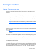
FC and FlexFabric bay configuration using multiple enclosures The VC-FC modules and FlexFabric FCoE or FC-configured uplinks do not support stacking. To ensure server profile mobility, the VC-FC and FlexFabric bay configurations must be identical for all enclosures in the domain. For example, in a multi-enclosure domain with a total of four enclosures, if bays 3 and 4 of the Primary Enclosure contain VC-FC modules, then bays 3 and 4 of Remote Enclosures 1, 2, and 3 must also contain VC-FC modules.
The following illustration shows an invalid VC-FC and FlexFabric bay configuration. For VC-FC bay compatibility, Bay 4 in Remote Enclosure 1 is empty, and Bay 3 of Remote Enclosure 2 has an Ethernet module present. For FlexFabric bay compatibility, Bay 2 in Remote Enclosure 1 is empty, and Bay 1 of Remote Enclosure 2 has an Ethernet module present.
Directly connecting VC domains In a multi-enclosure domain configuration with properly installed stacking cables, each network defined in the domain is available to all server profiles in the domain without requiring any additional uplink ports. This configuration enables you to establish an open communication path between two or more enclosures.
2. Prepare the VC-Enet module for installation (HP VC Flex-10 10Gb Ethernet Module shown). 3. Install the module into the interconnect bay (HP VC Flex-10 10Gb Ethernet Module shown). Push the module in slowly and smoothly until it is firmly seated. 4. If the Virtual Connect configuration includes three or more VC-Enet modules, install stacking links (typically 10GBASE-CX4 cables) between the modules. For more information, see "Connecting Virtual Connect Ethernet Module uplinks (on page 42)." 5.
6. Remove the perforated portion of the Default Network Setting label that extends beyond the faceplate of the primary module, or record the information contained on the label. The Default Network Settings label contains the DNS name, user name, and password of the primary interconnect module. This information is required for access to VCM. 7. Power on and configure the enclosure.
To install the component: 1. Remove the interconnect blank. NOTE: HP Virtual Connect works optimally in enclosures configured with HP Virtual Connect interconnect modules only. 2. Prepare the FlexFabric module for installation. (HP Virtual Connect FlexFabric 10/24-port Module shown).
3. Install the FlexFabric module into the interconnect bay. 4. If the enclosure configuration includes more than one VC module, connect any necessary stacking cables between the modules. The FlexFabric module supports stacking links for Ethernet traffic only. For more information, see the HP Virtual Connect for c-Class BladeSystem User Guide on the HP website (http://www.hp.com/go/vc/manuals). 5.
12. Before accessing VCM, verify that the HP BladeSystem Onboard Administrator firmware is at the recommended firmware version. For specific instructions, see the HP website (http://www.hp.com/go/oa). IMPORTANT: For proper Virtual Connect operation, always assign an IP address to each server blade iLO and interconnect module. 13. Verify that each server blade iLO and interconnect module has been assigned an IP address by reviewing the bay summary screens in the Onboard Administrator.
2. Prepare the VC-FC module for installation (HP Virtual Connect 4Gb Fibre Channel Module shown). 3. Install the VC-FC module into the interconnect bay (HP Virtual Connect 4Gb Fibre Channel Module shown). Push the module in slowly and smoothly until it is firmly seated. 4. Connect the data center SAN switch ports to the VC-FC module 1/2/4 Gb SFP ports. IMPORTANT: For proper thermal operation, always install SFP dust covers in SFP ports without SFP transceivers installed.
o If VC-Enet modules are installed in the same enclosure, use VCM to administer VC-FC modules. o If VC-Enet modules are not installed in the same enclosure, the VC-FC module operates in the default configuration only. Installing QSFP+, SFP+ or SFP transceivers WARNING: To avoid serious injury, never look directly into an open transceiver port.
Removing QSFP+, SFP+ or SFP transceivers WARNING: To avoid serious injury, never look directly into an open transceiver port. CAUTION: Disconnect all cables before removing or installing a QSFP+, SFP+ or SFP transceiver, because of the potential damage to the cables, the cable connector, or the optical interfaces in the transceiver. Do not remove and install transceivers more often than is necessary. Doing so can shorten the useful life of the transceiver. 1. Disconnect all cables. 2. Open the latch.
Connecting Virtual Connect Ethernet module uplinks Each interconnect module has several numbered Ethernet connectors. All of these connectors can be used to connect to data center switches (uplink ports), or they can be used to stack Virtual Connect modules as part of a single Virtual Connect domain (stacking ports). See "Recommended stacking connections (on page 23)." Networks must be defined within VCM so that specific named networks can be associated with specific external data center connections.
In this case, the Ethernet packets are passed unchanged between the server blades and the external networks. Any VLAN tags added by the server or external switch are ignored and pass through the VC-Enet modules. The previous figure also shows a local connection between Server Blade 2 and Server Blade 16, which might be used in a cluster or as a network heartbeat.
To make VCM aware of individual network connections, see "Define Ethernet Network screen" in the user guide. Mapping multiple networks to a single port in a shared uplink set The network administrator can choose to reduce the number of cables between the Virtual Connect enclosure and the data center switches by mapping multiple networks to a single, shared uplink port. In this case, a network is not just mapped to an uplink port, but to a VLAN on that port.
Network Shared uplink set and VLAN Production_Network Shared_Uplink_Set_A:VLAN_15 Dev_Network Shared_Uplink_Set_A:VLAN_21 Backup_Network Shared_Uplink_Set_A:VLAN_32 iSCSI_Storage_Network Shared_Uplink_Set_A:VLAN_76 In this example, all of the defined networks share a single active uplink port (such as Enclosure1:Bay1:PortX2) using VLAN tagging, while the second link in the shared uplink set is available for failover. The shared uplink set can also be constructed from multiple 1-Gb external ports.
By default, all ports on a Catalyst 4500/4000 switch and a Catalyst 6500/6000 switch use channel protocol PAgP and are not running LACP. For all ports concerned, you must change the channel mode to LACP. On switches running CatOS, you can only change channel mode per module. In the following example, change the channel mode for slots 1 and 2 by using the following command: set channelprotocol lacp module_number Verify the changes by using the following command: show channelprotocol.
channel-group 10 mode active ! interface GigabitEthernet7/48 description test-VC switchport switchport trunk encapsulation dot1q switchport trunk allowed vlan 10,20,30,40 switchport mode trunk no ip address speed 1000 channel-protocol lacp channel-group 10 mode active Failover and check-pointing VCM runs as a high-availability pair when VC-Enet modules are installed in horizontally adjacent interconnect bays. The active VCM is usually on the lowest odd numbered bay when the enclosure is powered up.
Interconnect module removal and replacement Virtual Connect modules It is not necessary to remove the module from the domain if the module is not in use. The module is removed automatically from the domain without user intervention. Replacing a primary or backup VC module with a different VC module type is not allowed without first deleting the domain.
Replacing an HP 4Gb VC-FC Module, HP VC 4Gb FC Module, or HP 8Gb 20-Port FC Module with an HP VC 8Gb 24-Port FC Module 1. Upgrade the VC domain firmware to the latest supported version. See "VC module supported firmware (on page 9)." 2. Verify that the replacement will result in a good configuration. See "Multiple enclosure requirements (on page 30)." 3. Verify that the user has server and storage role permissions. 4.
10. Re-assign the server profiles, and then add the FC connections to the profiles. Possible errors If the previous steps are not followed exactly, the module might be set to the UNKNOWN or INCOMPATIBLE state depending on how the error state was reached. Physically remove the module. Then, insert the correct module type. If the previous steps have been followed and the server is not connecting properly to the network, power down the server, and then power it back up.
3. If any Flex-10 NICs with profile connections are connected to the interconnect bays being upgraded, the profile connections must be removed. To remove a profile connection, unassign the profile (recommended) or delete the connection from the profile. 4. Remove all network uplinks from the modules to be removed. 5. Remove the existing modules from both horizontally adjacent bays. 6. Ensure that the modules are removed from the Virtual Connect GUI.
6. Reassign the server profiles or add the connections to the profiles, depending on what was done in step 1. Possible errors If the previous steps are not followed exactly, the newly inserted module might be set to the UNKNOWN or INCOMPATIBLE state, depending on how the error state was reached. To correct this error: 1. Physically remove the module. 2. Insert the original module. 3. Ensure that all profiles have been unassigned. 4. Remove the module. 5.
power-cycled while the credential recovery occurs, the MAC addresses and WWNs might be returned to the factory default settings.
HP Virtual Connect Manager Configuring browser support Access to the VCM GUI is provided through HTTPS (HTTP exchanged over an SSL-encrypted session) and requires HTTPS (port 443) to be enabled on the management network. The minimum supported screen resolution is 1024 x 768 with 256 colors. For optimal viewing, HP recommends setting the screen resolution to 1280 x 1024. Requirements The VCM web interface requires an XSLT-enabled browser with support for JavaScript 1.3 or the equivalent.
Pop-up windows must be enabled for certain features to function correctly. Check the browser settings to make sure pop-up blockers are not enabled before running the application. • Cookies Cookies must be enabled for certain features to function correctly. Check your browser settings to make sure cookies are enabled before running the application.
• Log on to the enclosure Onboard Administrator. From the rack overview screen, select the Virtual Connect Manager link from the left navigation tree. • Log on to the enclosure Onboard Administrator. To display the Interconnect Bays summary screen, select Interconnect Bays in the left navigation tree of the Onboard Administrator user interface. Select the Management URL link for the primary VC-Enet module.
Logging on to the HP Virtual Connect Manager GUI Log on using the user name (Administrator) and password. You can optionally specify the authentication method or VCM role at log on: • • To specify the authentication method (local, ldap, radius, tacacs), enter the authentication method followed by a colon before the user name. For example, ldap:user1. To specify the VCM role (domain, network, server, storage), enter the role followed by a colon before the user name. For example, network:user1.
• The attempted IP sign-in address is for a VC-Enet module not running the primary VCM. • The browser settings are incorrect. See "Configuring browser support (on page 54)." • You have entered an invalid role or authentication service name. • Authentication service is disabled, is not correctly configured, or is not up in the server. About HP Virtual Connect Manager To view detailed product information, select About HP Virtual Connect Manager from the Help pull-down menu.
networks, server profiles, and user accounts that simplify the setup and administration of server connections. Establishing a Virtual Connect domain enables you to upgrade, replace, or move servers within your enclosures without changes being visible to the external LAN/SAN environments. Beginning with VC 4.10, an auto-deployment feature allows for the configuration of a VC domain from a centralized location using DHCP and TFTP to access the configuration script.
If the wizard is canceled before the enclosure is imported, you are returned to the Virtual Connect Home page. To restart the wizard, select Domain Setup Wizard from the Tools menu on the home page. You must have domain privileges to access the Domain Setup Wizard. Local Enclosure To communicate with other VC modules and server blades, VCM requires the logon credentials for the local Onboard Administrator.
VCM creates a local user named "vcmuser" on the OA module. Do not modify the credentials for this user. Do not change the "local users" authentication setting for the OA module. Enclosure Import/Recovery After VCM has successfully established contact with the Onboard Administrator, you can create a Virtual Connect domain by importing the enclosure or by restoring a previously created Virtual Connect domain from a saved configuration file.
CAUTION: Restoring a Virtual Connect domain configuration from a backup file that was created on another Virtual Connect domain is not supported and can cause serious faults within this and other Virtual Connect Domains within the environment. The restore selection and configuration files should only be used to restore the same previously existing domain.
Enclosure Import After making the selection to create a new Virtual Connect domain by importing the enclosure on the Enclosure Import/Recovery screen, the Import Status screen appears and provides information about whether the import was successful. If the import is not successful, error information is displayed. Importing additional enclosures To import additional enclosures using the Domain Setup Wizard after the initial enclosure has been imported: 1. Select Tools > Domain Setup Wizard. 2.
6. Click Import. Using double-dense server blades Virtual Connect Manager supports the use of double-dense server blades, enabling support for up to 32 device bays in a single c7000 enclosure. This support also provides 32 new device bays (1A-16A and 1B-16B) for profile assignment. On a c3000 enclosure, this feature supports 8 additional or 16 total device bays.
When restoring from the configuration file, remote enclosure credentials are lost. See "Recovering remote enclosures (on page 58)." General Settings The Virtual Connect domain name should be unique within the data center, and can be up to 31 characters without spaces or special characters. The Domain Setup Wizard automatically assigns a domain name (enclosurename_vc_domain). This name can be changed when running the setup wizard, or at any time from the Domain Settings (Configuration) screen.
Local Users The first time this screen appears, the Administrator account, which has all administrative user role permissions, might be the only user listed. The Administrator account cannot be deleted or have domain user role permissions removed. However, the Administrator password can be changed, and the network, server, and storage user role permissions can be removed. The default Administrator password is identified on the Default Network Settings label on the primary VC module.
Click Apply to save your changes. • To set a session timeout period, enter a number between 10 and 1440 in the Session Timeout box. To disable a session timeout period, enter 0. Click Apply to save your changes. Any change in the timeout value affects all open sessions and is applied to new sessions. • To edit the delete confirmation preference, select or clear Auto Populate Name During Delete Confirmation, and then click Apply.
User Settings Observe the following user settings guidelines: • Username is a required field. • The Username field must contain an alpha-numeric value with 1 to 31 characters. • The Password field must contain an alpha-numeric value with 3 to 40 characters. The default password length is 8 characters.
Finish domain wizard Click Finish to complete this wizard, and then run the Network Setup Wizard ("HP Virtual Connect Network Setup Wizard" on page 69) to define the Ethernet networks that will be available within the Virtual Connect domain. Deselect the Start the Network Setup Wizard checkbox, and then click Finish to go to the Home page without running additional setup wizards.
IMPORTANT: For a Virtual Connect environment to operate properly, all HP Virtual Connect Ethernet modules within the Virtual Connect domain must be interconnected with stacking links. HP strongly recommends that redundancy be maintained in stacking links to ensure continued connectivity of servers to the external networks. For more information, see “Supported configurations (on page 16)" and “Recommended stacking connections (on page 23).
Always establish control processes to ensure that a unique MAC address range is used in each Virtual Connect domain in the environment. Reusing address ranges could result in server network outages caused by multiple servers having the same MAC addresses.
Select the type and range of MAC address, and then click Next. Selecting VC-assigned MAC address ranges When using VC-assigned MAC addresses, you can choose between using an HP pre-defined MAC address range or using a user-defined MAC address range. • HP pre-defined MAC address range (recommended). These pre-defined ranges are reserved and are not the factory default on any hardware. There are 64 ranges of 1024 unique addresses to choose from. Be sure to use each range only once within a data center.
NOTE: After any server profiles are deployed using a selected MAC address range, that range cannot be changed until all server profiles are deleted. Select the type and range of MAC address, and then click Next. Server VLAN Tag Settings VLAN tunneling support You can tunnel VLAN tags and map VLAN tags in the same domain. As of VC 3.30, tunneling and mapping is configured at the network level, not at the domain level.
maintain compatibility with VC 3.30 domains that have Legacy VLAN Capacity mode enabled, the VCM CLI maintains the current functionality for the VLAN mode. This also allows the use of existing scripts that manipulate the VLAN capacity. Enabling expanded VLAN capacity on a domain is non-disruptive. Expanded VLAN Capacity mode allows up to 1000 VLANs per domain. The number of VLANs per shared uplink set is restricted to 1000.
Dual Port FlexFabric 20 Gb FlexFabric Adapters, the range is limited to 1 Gb to 20 Gb in 100 Mb increments. For more information on FlexNICs, see the HP Virtual Connect for c-Class BladeSystem User Guide on the HP website (http://www.hp.com/go/vc/manuals).
To determine the types of network connections to use, see "Connecting Virtual Connect Ethernet module uplinks (on page 42).
To define a network: 1. Enter a name for the network that will be easily understood and recognized by the server administrators defining and deploying server profiles. The network name can be up to 64 characters in length (no spaces). 2. To add a color to the network, select a color from the Color pull-down menu. The network color is used as a visual identifier for the network within VCM. 3. To add labels to the network, type a label in the Labels field, and then press Enter.
To change these settings: 1. Click the selection box, and then select a setting (100Mb to 20Gb): o Set preferred connection speed. This value is the default speed for server profile connections mapped to this network. The server administrator can increase or decrease this setting on an individual profile connection. This setting is used for the minimum bandwidth. o Set maximum connection speed. This value is the maximum speed for server profile connections mapped to this network.
Define Shared Uplink Set Connection To define multiple networks that share a common set of external uplink ports: 1. Enter an overall name for the set of shared uplinks (up to 64 characters, no spaces). 2. Set the connection mode to Auto or Failover. 3. If the connection mode is set to Auto, set the length of the LACP Timer. 4. From the Add Port list, select the external uplink ports that will carry these networks. To delete a port, click the Delete link in the Action column of the row to delete.
d. To add labels to the network, type a label in the Labels field, and then press Enter. Labels are used as text-based identifiers for the network within VCM. Each label can contain up to 24 characters, excluding spaces. Each network can have up to 16 labels. e. To set a custom value for the preferred link connection speed or maximum link speed, click Advanced Network Settings. For more information, see "Advanced Network Settings (on page 77)." f. 6. Click Apply.
Add an Associated FCoE Network. Add a single Associated Network.
Add multiple Associated Networks. Defined Network Connections This summary screen displays the external connections for each defined network.
For more information about the data displayed on this screen, see "Ethernet Networks (External Connections) screen" in the user guide. To define additional networks in the domain, click Create more networks. To complete the Network Setup Wizard, click Done. To view a filtered list of created networks, click Filter, select the criteria, and then click Go. To return to the full list, click X.
Select Ethernet Network from the Define pull-down menu. HP Virtual Connect Fibre Channel Setup Wizard This wizard configures external Fibre Channel connectivity for the HP BladeSystem c-Class enclosure using HP Virtual Connect. A user account with storage privileges is required to perform these operations. Use this wizard to do the following: • Identify WWNs to be used on the server blades deployed within this Virtual Connect domain. • Define fabrics.
To initiate this wizard, click the Fibre Channel Wizard link on the homepage, or select Fibre Channel Setup Wizard from the Tools pull-down menu. You must have storage privileges to access the Fibre Channel Setup Wizard. WWN settings At this point in the wizard, you are asked to select the type of FC WWNs to be used on the server blades within the enclosure. You can choose to use the server factory default WWNs provided with the FC HBA mezzanine card or to use FC WWNs assigned by Virtual Connect.
Assigned WWNs HP Virtual Connect Manager 86
The WWN range used by the Virtual Connect domain must be unique within the environment. HP provides a set of pre-defined ranges that are reserved for use by Virtual Connect and do not conflict with server factory default WWNs. When using the HP-defined WWN ranges, be sure that each range is used only once within the environment. Select the type and range of WWNs, and then click Next. Define Fabric To define a fabric, select the Define Fabric checkbox, and then click Next.
Define SAN Fabric To define the SAN fabric: 1. Name the fabric. Do not use spaces. 2. Select the uplink ports to be used. Only uplinks on the same bay can be in the same SAN fabric. 3. If the uplink ports selected are FlexFabric module ports, select the fabric type. Supported fabric types are FabricAttach and DirectAttach. o Select FabricAttach if the FlexFabric module is connected using traditional SAN switches.
Advanced SAN Fabric Settings Login Re-Distribution When creating or editing a SAN fabric using HP VC FlexFabric Modules in a FabricAttach fabric, select the Show Advanced Settings checkbox to select the login re-distribution: • Manual Login Re-Distribution—Default for all FC modules. You must initiate a Login Re-Distribution request through the VC GUI or CLI interfaces.
Defined SAN Fabric This screen lists the SAN fabrics currently defined for this domain. Select Yes to define additional fabrics, or No if you have defined all available fabrics, and then click Next. Finish Fibre Channel wizard When the Fibre Channel Setup Wizard completes, server profiles can be defined and associated with server blades. To begin deploying server blades: 1. Be sure the Start the Server Profile Wizard check box is selected. 2. Click Finish.
HP Virtual Connect Manager Server Profile Setup Wizard This wizard enables you to setup and configure network/SAN connections for the server blades within the enclosure. Use the wizard to define a server profile template that identifies the server connectivity to use on server blades within the enclosure. Then use the template to create and apply server profiles to up to 16 server blades automatically. Once created, the individual server profiles can be edited independently.
By configuring VCM to assign serial numbers, a profile can present a single serial number regardless of the physical server. With these configuration values added to server profiles, software that is licensed to a particular server, based on one or both of these values, can be migrated to new server hardware without re-licensing the software for the new server hardware. This feature prevents you from having to reinstall serial number sensitive software after a system recovery.
For more information on defining a server profile and advanced profile settings, see the HP Virtual Connect for c-Class BladeSystem User Guide on the HP website (http://www.hp.com/go/vc/manuals). Server profile troubleshooting In some cases, server profiles can be assigned to server blades when certain mismatches exist between the server profile definition and the server blade.
• If the number of FCoE connections in the profile is more than the number of available FCoE ports on the server, the profile assignment succeeds, but the connections display a statue of "Not mapped" when you view the profile. IMPORTANT: Disabling a server port by entering the iLO Remote Console, rebooting the server, and then using the F9 key to enter RBSU causes a "Profile pending" status for a server profile when a VCM failover occurs.
• Single enclosure domain HP Virtual Connect Manager 95
• Multi-enclosure domain Name Server Profiles The table displays the automatically generated names that will be assigned to the new server profiles. The server profile name can be up to 64 characters in length (no spaces). Because the server profile can be assigned to different locations, HP recommends that the name reflect the server function. For each enclosure, a base name is provided. You can use this enclosure name to create names for the profiles assigned to the enclosure.
• Single enclosure domain • Multi-enclosure domain Create Server Profiles This screen provides confirmation of each profile that was created and successfully assigned (if applicable).
Click Start Over to create additional profiles using the wizard. This option returns you to the appropriate step for creating more profiles. Click Finish if you are finished creating profiles at this time. This option launches the Virtual Connect Home page. If creation of a server profile failed, see "Server profile troubleshooting (on page 93).
Verify link and speed To verify that all external ports connected to the data center are linked and are operating at the appropriate speed: 1. Verify that all VC-Enet and FlexFabric modules are powered on and functioning properly. The module status LED should be green for all modules connected and configured in Virtual Connect for data center use. If the LED is not green, use the HP Onboard Administrator user interface to diagnose the problem and verify that the module is powered on. 2.
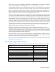
Component identification HP Virtual Connect Flex-10 10Gb Ethernet Module components and LEDs HP Virtual Connect Flex-10 10Gb Ethernet Module components Item Description 1 Port X1 (10GBASE-CX4), multiplexed with item 4 2 USB 2.
HP Virtual Connect Flex-10 10Gb Ethernet Module LEDs Item LED description Status 1 Module locator (UID) Blue = Module ID is selected. Off = Module ID is not selected. 2 Module status Green = Normal operation Amber = Degraded condition Amber flashing = Fault condition Off = Power off 3 X1 port status (10GBASE-CX4) Green = Port is configured and operating as an uplink port connected to a data center fabric. Amber = Port is operating as a stacking link interconnecting Virtual Connect modules.
Item LED description Status 8 X7/X8 port status Green = Port is configured and operating as an uplink port connected to a data center fabric. Amber = Port is operating as a stacking link interconnecting Virtual Connect modules. Blue = Port locator (PID) Off = Unconfigured 9 X1/X6 port status Green = Port is configured and operating as an uplink port connected to a data center fabric. Amber = Port is operating as a stacking link interconnecting Virtual Connect modules.
HP Virtual Connect Flex-10 10Gb Ethernet Module system maintenance switch Switch Default Function 1 Off Off = Normal operation On = Restore factory default login and DNS information* 2 Off Reserved 3 Off Reserved 4 Off Reserved *See "Resetting the Administrator password and DNS settings (on page 124).
HP Virtual Connect Flex-10/10D Module components and LEDs HP Virtual Connect Flex10/10D Module components Ports X1 through X10 support Ethernet traffic only. Item Component Description 1 For support purposes only 2 USB 2.
Item LED description Status 1 Module locator (UID) Blue = Module ID is selected. Off = Module ID is not selected. 2 Module status Green = Normal operation Amber = Degraded condition Amber flashing = Fault condition Off = Power off 3 X1–X10 link/port activity Green = 10G link Green flashing = 10G activity Amber = 1G link Amber flashing = 1G activity Off = No link 4 X1–X10 port status Green = Port is configured and operating as an uplink port connected to a data center fabric.
HP Virtual Connect Flex10/10D Module system maintenance switch Switch Default Function 1 Off Off = Normal operation On = Restore factory default login and DNS information* 2 Off Reserved 3 Off Reserved 4 Off Reserved *See "Resetting the Administrator password and DNS settings (on page 124).
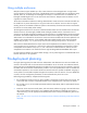
HP Virtual Connect FlexFabric-20/40 F8 Module components and LEDs HP Virtual Connect FlexFabric-20/40 F8 Module components Ports Q1 through Q4 support Ethernet. Ports X1 through X8 support Ethernet and Fibre Channel traffic. Port pairs X5/X6 and X7/X8 carry a single type of network traffic, either Ethernet or Fibre Channel.
Item Description Capable speed 14 Port X5 SFP+ connector** † 1Gb, 10Gb Ethernet 2Gb, 4Gb, or 8Gb FC *QSFP+ Supports 1x40Gb QSFP+ SR4, 1x40Gb QSFP+ SR4 300m, 1x40Gb QSFP+ LR4, 1x40Gb QSFP+ AOC SR4, 1x40Gb QSFP+ DAC CR4, and 40Gb QSFP+ to 4xSFP+ Splitter. 10Gb SFP+ pluggable Ethernet transceiver modules can be used in QSFP+ ports by using the HP BLc QSFP+ to SFP+ Adapter. LRM, 1Gb, FC, 15m active DAC, and 7m passive DAC SFP+ pluggable modules are not supported with the adapter in QSFP+ ports.
Item LED description Status 2 Module status Green = Normal operation Amber = Degraded condition Amber flashing = Fault condition Off = Power off 3 L/A Green = Port LEDs are in Link/Activity mode 4 PID Green = Port LEDs are in Port Identifier mode 5 FC Mode Green = Port LEDs are in FC mode 6 Ethernet Green = Port LEDs are in Ethernet mode 7 8 9 10 11 12 13 14 X1-X8 port status PID mode The PID mode LED is lit green.
Item LED description Status link (Qn.1–Qn.4). PID mode The PID mode LED is lit green. Port LEDs: Amber = Port is configured as an Enet stacking link. Green = Port is configured as an Enet uplink port Light Purple = port is configured as an Enet mirror-to-port Red = Port has an error such as an invalid or unsupported pluggable module detected Blue = Port identification (locator) L/A mode The L/A mode LED is lit green.
HP Virtual Connect FlexFabric-20/40 F8 Module system maintenance switch Switch Default Function 1 Off Off = Normal operation On = Restore factory default login and DNS information* 2 Off Reserved 3 Off Reserved 4 Off Reserved *See "Resetting the Administrator password and DNS settings (on page 124).
HP Virtual Connect FlexFabric 10Gb/24-port Module components and LEDs HP Virtual Connect FlexFabric 10Gb/24-port Module components Ports X1 through X4 support Ethernet or Fibre Channel traffic. Ports X5 through X8 support Ethernet traffic only. Ports X7 and X8 are multiplexed with the internal 10Gb interface cross-link. Item Description Capable speed 1 — 2 USB 2.
Item LED description Status 1 Module locator (UID) Blue = Module ID is selected. Off = Module ID is not selected. 2 Module status Green = Normal operation Amber = Degraded condition Amber flashing = Fault condition Off = Power off 3 5 7 9 X1-X4 port status Ethernet mode Green = Port is configured and operating as an uplink port connected to a data center fabric. Amber = Port is operating as a stacking link interconnecting Virtual Connect modules.
Item LED description Status 11 13 15 17 X5-X8 port status Green = Port is configured and operating as an uplink port connected to a data center fabric. Amber = Port is operating as a stacking link interconnecting Virtual Connect modules. Amber flashing = SFP module is invalid for Ethernet mode. Purple flashing = Port is configured as a mirror to port.
HP Virtual Connect FlexFabric 10Gb/24-port Module system maintenance switch Switch Default Function 1 Off Off = Normal operation On = Restore factory default login and DNS information* 2 Off Reserved 3 Off Reserved 4 Off Reserved *See "Resetting the Administrator password and DNS settings (on page 124).
HP Virtual Connect 4Gb FC Module (with enhanced NPIV) components and LEDs HP Virtual Connect 4Gb FC Module components Item Description Device bays supported in default configuration 1 2/4 Gb capable SFP connectors 1-16 (c7000) 1-8 (c3000) 2 Reset button (recessed) — In the default configuration (before a Virtual Connect domain is created), all 2/4 Gb capable uplink ports are grouped into an Uplink Port Group and dynamically distribute connectivity from all server blades.
HP Virtual Connect 4Gb FC Module LEDs Item LED description Status 1 Module locator (UID) Blue = Module ID selected Off = Module ID not selected 2 Module status Green = Normal operation Amber = Degraded condition Off = Power off 3 Port Green = Port is configured as the uplink for one or more server HBAs. Amber = Port is not configured. Blue = Port is selected.
HP Virtual Connect 4Gb FC Module system maintenance switch Switch Default Function 1 Off Reserved 2 Off Reserved 3 Off Reserved 4 Off Reserved When part of a Virtual Connect domain, Virtual Connect Manager overrides any system maintenance switch settings.
HP Virtual Connect 8Gb 24-Port Fibre Channel Module components and LEDs HP VC 8Gb 24-Port FC Module components Item Description 1 SFP/SFP+ ports supporting 8Gb SFP+ and 1-16 4Gb SFP transceivers Reset button (recessed) — 2 Device bays supported when in default configuration Component identification 119
HP VC 8Gb 24-Port FC Module LEDs Item LED description Status 1 Module locator (UID) Blue = Module ID selected Off = Module ID not selected 2 Module status Green = Normal operation Amber = Degraded condition Off = Power off 3 Port link/activity Green = Port is online, but not passing traffic Green slow flashing = Port is online and not logged in Green flickering = Port is online passing traffic Amber = Port has light or signal, but not yet online Amber slow flashing = Port is disabled (NPIV not e
HP VC 8Gb 24-Port FC Module system maintenance switch Switch Default Function 1 Off Reserved (must be in "Off" position) 2 Off Reserved (must be in "Off" position) 3 Off Reserved (must be in "Off" position) 4 Off Off = Module debug and test interface is inaccessible. On = Module debug and test interface is accessible. When part of a Virtual Connect domain, Virtual Connect Manager overrides any system maintenance switch settings.
HP Virtual Connect 8Gb 20-Port Fibre Channel Module components and LEDs HP VC 8Gb 20-Port FC Module components Item Description Device bays supported in default configuration 1 SFP/SFP+ ports supporting 8Gb SFP+ and 1-16 (c7000) 4Gb SFP transceivers 1-8 (c3000) 2 Reset button (recessed) — In the default configuration, before a Virtual Connect domain is created, all uplink ports are grouped into an uplink port group and dynamically distribute connectivity from all server blades.
Item LED description Status 1 Module locator (UID) Blue = Module ID is selected. Off = Module ID is not selected. 2 Module status Green = Normal operation Amber = Degraded condition Off = Power off 3 Logged in Green = Logged in to an external Fibre Channel switch port Off = Port down, offline, no sync, or error 4 Activity Green flashing (variable) = Link activity Green flashing (1 Hz) = External fabric switch does not support NPIV.
Resetting the Administrator password and DNS settings To return the VC-Enet module to factory default settings for the Administrator password and DNS settings, you must access the system maintenance switch. For switch locations, see the appropriate module system maintenance switch information.
15. Change the Administrator password.
Regulatory information Safety and regulatory compliance For safety, environmental, and regulatory information, see Safety and Compliance Information for Server, Storage, Power, Networking, and Rack Products, available at the HP website (http://www.hp.com/support/Safety-Compliance-EnterpriseProducts). Belarus Kazakhstan Russia marking Manufacturer Hewlett-Packard Company, Address: 3000 Hanover Street, Palo Alto, California 94304, U.S.
Valid date formats include the following: • YWW, where Y indicates the year counting from within each new decade, with 2000 as the starting point. For example, 238: 2 for 2002 and 38 for the week of September 9. In addition, 2010 is indicated by 0, 2011 by 1, 2012 by 2, 2013 by 3, and so forth. • YYWW, where YY indicates the year, using a base year of 2000. For example, 0238: 02 for 2002 and 38 for the week of September 9.
Electrostatic discharge Preventing electrostatic discharge To prevent damaging the system, be aware of the precautions you need to follow when setting up the system or handling parts. A discharge of static electricity from a finger or other conductor may damage system boards or other static-sensitive devices. This type of damage may reduce the life expectancy of the device. To prevent electrostatic damage: • Avoid hand contact by transporting and storing products in static-safe containers.
Support and other resources Before you contact HP Be sure to have the following information available before you call HP: • Active Health System log (HP ProLiant Gen8 or later products) Download and have available an Active Health System log for 3 days before the failure was detected. For more information, see the HP iLO 4 User Guide or HP Intelligent Provisioning User Guide on the HP website (http://www.hp.com/go/ilo/docs).
providers or service partners) identifies that the repair can be accomplished by the use of a CSR part, HP will ship that part directly to you for replacement. There are two categories of CSR parts: • Mandatory—Parts for which customer self repair is mandatory. If you request HP to replace these parts, you will be charged for the travel and labor costs of this service. • Optional—Parts for which customer self repair is optional. These parts are also designed for customer self repair.
Pour plus d'informations sur le programme CSR de HP, contactez votre Mainteneur Agrée local. Pour plus d'informations sur ce programme en Amérique du Nord, consultez le site Web HP (http://www.hp.com/go/selfrepair). Riparazione da parte del cliente Per abbreviare i tempi di riparazione e garantire una maggiore flessibilità nella sostituzione di parti difettose, i prodotti HP sono realizzati con numerosi componenti che possono essere riparati direttamente dal cliente (CSR, Customer Self Repair).
HINWEIS: Einige Teile sind nicht für Customer Self Repair ausgelegt. Um den Garantieanspruch des Kunden zu erfüllen, muss das Teil von einem HP Servicepartner ersetzt werden. Im illustrierten Teilekatalog sind diese Teile mit „No“ bzw. „Nein“ gekennzeichnet. CSR-Teile werden abhängig von der Verfügbarkeit und vom Lieferziel am folgenden Geschäftstag geliefert. Für bestimmte Standorte ist eine Lieferung am selben Tag oder innerhalb von vier Stunden gegen einen Aufpreis verfügbar.
sustituciones que lleve a cabo el cliente, HP se hará cargo de todos los gastos de envío y devolución de componentes y escogerá la empresa de transporte que se utilice para dicho servicio. Para obtener más información acerca del programa de Reparaciones del propio cliente de HP, póngase en contacto con su proveedor de servicios local. Si está interesado en el programa para Norteamérica, visite la página web de HP siguiente (http://www.hp.com/go/selfrepair).
Opcional – Peças cujo reparo feito pelo cliente é opcional. Essas peças também são projetadas para o reparo feito pelo cliente. No entanto, se desejar que a HP as substitua, pode haver ou não a cobrança de taxa adicional, dependendo do tipo de serviço de garantia destinado ao produto. OBSERVAÇÃO: Algumas peças da HP não são projetadas para o reparo feito pelo cliente. A fim de cumprir a garantia do cliente, a HP exige que um técnico autorizado substitua a peça.
Support and other resources 135
Support and other resources 136
Acronyms and abbreviations BPDU Bridge Protocol Data Unit DAC direct attach cable DHCP Dynamic Host Configuration Protocol DNS domain name system FC Fibre Channel FCoE Fibre Channel over Ethernet HBA host bus adapter iSCSI Internet Small Computer System Interface LACP Link Aggregation Control Protocol LAG link aggregation group LLDP Link Layer Discovery Protocol MAC Media Access Control Acronyms and abbreviations 137
MIB management information base NPIV N_Port ID Virtualization OA Onboard Administrator POST Power-On Self Test RDP Rapid Deployment Pack SFP small form-factor pluggable SSL Secure Sockets Layer TFTP Trivial File Transfer Protocol USB universal serial bus VCDG Virtual Connect Domain Group VCEM Virtual Connect Enterprise Manager VCM Virtual Connect Manager VCSU Virtual Connect Support Utility VLAN virtual local-area network Acronyms and abbreviations 138
WWN World Wide Name XFP 10 Gb small form factor pluggable Acronyms and abbreviations 139
Documentation feedback HP is committed to providing documentation that meets your needs. To help us improve the documentation, send any errors, suggestions, or comments to Documentation Feedback (mailto:docsfeedback@hp.com). Include the document title and part number, version number, or the URL when submitting your feedback.
Index A About menu 58 accessing HP Virtual Connect Manager 11, 55 ActiveX 54 adding enclosures 63 Advanced Network Settings 77 allowing double density device bays 61 assign server profiles 94 assigned MAC addresses 70, 72 assigned WWNs 86 authorized reseller 129 B backup module 11, 15, 28 bay configuration guidelines 19 browser requirements 54 BSMI notice 126 buttons 100 C cabling 23, 42 Canadian notice 126 check-pointing 47 Cisco Core switch 45 CLI (Command Line Interface) 56 command line interface, usin
FC module bay configuration, multiple enclosures 31 FC module, installing 38 Federal Communications Commission (FCC) notice 126 Fibre Channel settings (WWN) 85 finish wizard 69, 83, 90 firmware, Onboard Administrator requirements 55 Flex-10 installation guidelines 20 FlexFabric module bay configuration, multiple enclosures 31 FlexFabric module, installation 35 FlexNIC 8 G general settings 65 grounding methods 128 H hardware setup 11, 33, 35, 38 help resources 129 high availability support 23, 47 HP techni
M MAC address settings 70 modifications, FCC notice 126 module configuration, default 12 module removal and replacement 48 Mozilla support 54 multiple enclosures, adding and importing 63 multiple enclosures, FC module bay configuration 31 multiple enclosures, FlexFabric module bay configuration 31 multiple enclosures, managing 10, 28 multiple enclosures, using 10 N name server profiles 96 native VLAN 79 network mapping 42 node WWN 85 NPIV 15 O Onboard Administrator login credentials 60 Onboard Administrat
Upgrading to an HP Virtual Connect FlexFabric Module from a VC-FC module 52 user accounts 66 user settings 68 using multiple enclosures 10 V VC domains, directly connecting 33 VC-assigned MAC addresses 72 verify data center connections 98 verify link and speed 99 verify network status 99 Virtual Connect documentation 6 Virtual Connect Manager setup overview 13 Virtual Connect overview 8 VLAN tagging 42, 73 VLAN tunneling, enable or disable 76 W website, HP 129 WWN settings 85 WWN, selecting a range 86 In