
VLS9200 user guide (BW402-10009, August 2012)


4. Disconnect all power cords from the node.
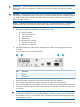
5. From the back of the node, make a note of all cable connections then disconnect the cables.
6. Remove the node from the front of the chassis. See “Replacing a Primary Node” (page 203)
for details.
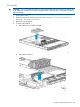
7. Install the replacement VLS9200 node into the rack.
8. Reconnect the cables to the new node.
The VLS9200 master node does not need the USB dongle. The Ethernet switch cables should
now connect to NIC ports 3 and 4.
9. Reconnect the power cords to the node.
10. Power up the node.
11. Insert the Quick Restore DVD into the drive and start the Quick Restore process. When the
Quick Restore is complete, the node will automatically reboot.
12. Repeat Step 4 through Step 11 for all secondary nodes.
13. When the master node comes up after the reboot, configure it as you would configure a new
VLS installation. See “Configuring the Primary Node 0” (page 42) for details. The node will
reboot after the configuration is set.
14. After the master node comes up after the reboot, configure each secondary node as you would
configure a new VLS installation. See “Configuring the Secondary Nodes” (page 42) for
details.
15. Log into Command View VLS to ensure that all secondary nodes have come up. (It does not
matter if they show a degraded state.)
16. Install the hp_6.1.0_reboot_3053 patch to the system; this will adjust the new backend Ethernet
configuration on each node. See the HP Virtual Library System hp_6.1.0_reboot_3053 Patch
Release Notes for details.
17. After the automatic reboot from the patch, log back into Command View VLS.
18. If any of the secondary nodes show a degraded state, run the Clear All Faults task on the
Chassis screen.
All nodes should now be up and in the green Good state.
Fibre Channel Switch Replacement
To replace a Fibre Channel Switch:
1. Power off the switch.
2. Make a note of all cable connections to the switch then disconnect the cables.
3. Remove the 1U cover plate for the switch from the front of the rack.
4. Remove the four bolts from the rail flanges on the rear rack uprights using a #2 Phillips
screwdriver.
5. Loosen the two nuts securing the rail ends to the adjustable mounting flanges, which are
mounted on the front rack uprights, using a 7/16 inch wrench.
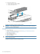
6. Slide the switch out the rear of the rack.
CAUTION: Make sure the switch is supported below, either by equipment mounted in the
next rack slot or with your hand, before sliding the switch off the adjustable mounting flanges
that support it.
7. Disconnect the AC power cables from the back of the switch.
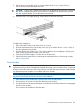
8. Remove the rack rails from the switch.
9. Install the rack rails on the new switch and then mount the switch in the rack. See Installing
the Fibre Channel Switch 8/24q into a Rack.
10. Reconnect all cables to the new switch exactly as they were connected to the failed switch.
11. Re-install the 1U cover plate for the switch to the front of the rack.
Fibre Channel Switch Replacement 205