
VLS9200 user guide (BW402-10009, August 2012)

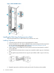


4. Tighten all four screws.
5. Repeat this procedure to install up to two more capacity enclosure above the previous one.
6. At the top of the capacity enclosures, install the base enclosure.
7. Install the remaining base and capacity enclosures:
• If you are installing four full arrays, continue installing three capacity enclosures beneath
each base enclosure working up the rack.
• If you are installing fewer than four full arrays, begin at rack position 17. Count down
two rack positions for each available capacity enclosure and begin installing them at the
lowest point. Then install the base enclosure at positions 17 and 18.
Repeat this to add a third base enclosure, if available, at rack positions 25 and 26, and
for a fourth base enclosure, if available, at positions 33 and 34.
When you have completed the installation, you will have all full arrays at the bottom. A
partial array will be at the top of the enclosures with empty space for the “missing”
enclosures. This allows room to add capacity enclosures without needing to reinstall the
existing enclosures.
Installing the Enclosure Power Cables
NOTE: When powering up (connecting the power cords) on a new array, power up the capacity
enclosures before the base enclosure.
To connect enclosure power cables:
1. Locate the AC power cords.
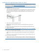
2. Connect a black power cable to the left power supply of each enclosure, route the cables
through the left side of the rack, and plug them into a PDM mounted on the left vertical post.
3. Connect a gray power cable to the right power supply of each enclosure, route the cables
through the right side of the rack, and plug them into a PDM mounted on the right vertical
post.
IMPORTANT: Equally distribute the current between the PDMs.
Cabling Base and Capacity Enclosures
26 Hardware Installation