
VLS9200 user guide (BW402-10009, August 2012)

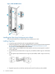


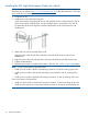

Table 1 Cabling the Base Enclosure
Connects toDescriptionItem
Array 1 base enclosure: connects to port 9 of Fibre Channel switch #1 (FC SW1)
via FC cable.
FC port 11
Additional base enclosures: connects to the next available port on Fibre Channel
switch #1 (FC SW1) via FC cable. Cable additional base enclosures to the switch
ports in this order: 19, 8, 18, 7, 17, 6, 16.
Array 1 base enclosure: connects to port 9 of Fibre Channel switch #2 (FC SW2)
via FC cable.
FC port 12
Additional base enclosures: connects to the next available port on Fibre Channel
switch #2 (FC SW2) via FC cable. Cable additional base enclosures to the switch
ports in this order: 19, 8, 18, 7, 17, 6, 16.
Array 1 base enclosure: connects to port 19 of Ethernet switch #2 (SW2).Ethernet port3
Additional base enclosures: connects to the next available port on Ethernet switch
#2 (SW2) via Ethernet cable. Cable additional base enclosures to the switch ports
in this order: 20, 17, 18, 15, 16, 13, 14.
Array 1 base enclosure: connects to port 19 of Ethernet switch #1 (SW1).Ethernet port4
Additional base enclosures: connects to the next available port on Ethernet switch
#1 (SW1) via Ethernet cable. Cable additional base enclosures to the switch ports
in this order: 20, 17, 18, 15, 16, 13, 14.
If you are installing a single base enclosure, cable it to the Fibre Channel and Ethernet switches
as indicated in Table 1 (page 27) and the installation is complete. Otherwise, continue to
Table 2 (page 27) and the procedure that follows it.
Table 2 Cabling Capacity Enclosures
Connects toDescriptionItem
SAS port 0, input port, of capacity controller 1 of
capacity enclosure 0
SAS cable connected to SAS port 0 of RAID controller
1 of base enclosure
5
SAS port 0, input port, of capacity controller 2 of
capacity enclosure 0
SAS cable connected to SAS port 0 of RAID controller
2 of base enclosure
6
SAS port 0, input port, of capacity controller 1 of
capacity enclosure 1 (if available)
SAS cable connected to SAS port 1, output port, of
capacity controller 1 of capacity enclosure 0
7
SAS port 0, input port, of capacity controller 2 of
capacity enclosure 1 (if available)
SAS cable connected to SAS port 1, output port, of
capacity controller 2 of capacity enclosure 0
8
SAS port 0, input port, of capacity controller 1 of
capacity enclosure 2 (if available)
SAS cable connected to SAS port 1, output port, of
capacity controller 1 of capacity enclosure 1
9
SAS port 0, input port, of capacity controller 2 of
capacity enclosure 2 (if available)
SAS cable connected to SAS port 1, output port, of
capacity controller 2 of capacity enclosure 1
10
NOTE: The base enclosure is on the top of the stack of capacity enclosures. From the top to the
bottom they are: base enclosure, capacity enclosure 0, capacity enclosure 1, capacity enclosure
2. One base enclosure and three capacity enclosures make up an array.
1. Locate the SAS cables included in the capacity enclosure kit contents.
2. Remove the tape and end caps from the SAS cables before installing.
3. Verify that both power cords are unplugged on each enclosure in the rack.
4. For each base enclosure, using the figure and table above, work downward to connect the
base enclosure to up to three capacity enclosures.
5. Secure the SAS cables of the enclosures together with a Velcro® tie.
Cabling Base and Capacity Enclosures 27