
VLS9200 user guide (BW402-10009, August 2012)


Cabling the High Performance Node
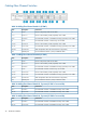
Table 4 Cabling the Node
Connects toDescriptionItem
Primary node: connects to port 0 of Fibre Channel switch #2 in rack 1 (FC SW2)
via FC cable.
FC storage port 21
Secondary nodes: connects to the next available port on Fibre Channel switch #2
(FC SW2) via FC cable. Cable secondary nodes to the switch ports in this order:
10, 1, 11, 2, 12, 3, 13.
Primary node: connects to port 0 of Fibre Channel switch #1 in rack 1 (FC SW1)
via FC cable.
FC storage port 12
Secondary nodes: connects to the next available port on Fibre Channel switch #1
(FC SW1) via FC cable. Cable secondary nodes to the switch ports in this order:
10, 1, 11, 2, 12, 3, 13.
Primary node: connects to your system's external network via FC cable.FC host ports 1–43
Secondary nodes: connects to your system's external network via FC cable.
Must always connect to the customer-provided external network via Ethernet cable.NIC 14
Secondary nodes: connects to the customer-provided external network when using
replication via Ethernet cable.
Primary node: connects to port 1 of Ethernet switch #1 (SW1) via Ethernet cable.NIC 35
Secondary nodes: connects to the next available port on Ethernet switch #1 (SW1)
via Ethernet cable. Cable secondary nodes to the switch ports 2 through 8 in
sequential order.
Primary node: connects to port 1 of Ethernet switch #2 (SW2) via Ethernet cable.NIC 46
Secondary nodes: connects to the next available port on Ethernet switch #2 (SW2)
via Ethernet cable. Cable secondary nodes to the switch ports 2 through 8 in
sequential order.
NOTE: Not all systems use all of the components listed in Table 4 (page 31).
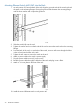
The primary node, node 0, is on the bottom of the stack of nodes. From the bottom to the top they
are: node 0, node 1, node 2, node 3. (The number of nodes will vary from system to system.)
1. Cable the primary node using Table 4 (page 31).
2. If you are installing more than one node, cable the nodes using Table 4 (page 31). Start at
node 1 just above the primary node (node 0) and work your way up the rack.
3. Using Velcro®, secure the cables to the left side of the rack.
4. Install loopback plugs on the nodes in all unused Fibre Channel ports.
Cabling the High Performance Node 31