
VLS9200 user guide (BW402-10009, August 2012)


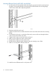


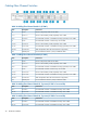

Table 8 Cabling Ethernet Switch #4, if present (SW2 of a second kit)
Connects toDescriptionItem
Ethernet port of RAID Controller 1 of additional base array enclosures via
Ethernet cable
Ports 17–2017–20
NOTE: Ethernet switch #1 is on the bottom and switch #2 is on the top. If present, Ethernet switch
#3 is on the bottom and switch #4 is on the top.
1. Connect the Ethernet switches to each other and to the Fibre Channel switches using
Table 5 (page 35) and Table 6 (page 35).
2. Connect the Ethernet switches to the nodes and base array enclosures if not already connected.
If installing multiple arrays:
a. Connect an Ethernet cable from Ethernet switch #1 to RAID controller 2 of additional
arrays in order (array 1, array 2, etc.). Use the switch #1 ports in this order: 20, 17, 18,
15, 16, 13, 14.
b. Connect an Ethernet cable from Ethernet switch #2 to RAID controller 1 of additional
arrays in order (array 1, array 2, etc.). Use the switch #2 ports in this order: 20, 17, 18,
15, 16, 13, 14.
NOTE: Each rack supports up to four arrays.
3. If installing a second connectivity kit in rack 4:
a. Connect an Ethernet cable from Ethernet switch #3 to RAID controller 2 of additional
arrays in order (array 13, array 14, etc.). Use the switch #3 ports in this order: 19, 20,
17, 18.
b. Connect an Ethernet cable from Ethernet switch #4 to RAID controller 1 of additional
arrays in order (array 13, array 14, etc.). Use the switch #4 ports in this order: 19, 20,
17, 18.
WARNING! Do not connect cables to unused ports on Ethernet switch #1 or #2. Doing so could
result in data loss.
NOTE: Do not secure the Ethernet cables at this time. You will secure them with the Fibre Channel
cables.
Installing the Ethernet Switch 2510–24 into a Rack
VLS9200 Entry-level systems use the Ethernet Switch 2510–24. No other switches are required.
NOTE: There are no rails associated with this switch.
36 Hardware Installation